
Frequency based modulator compensation

a modulator and frequency technology, applied in the field of frequency based modulator compensation, can solve the problems of affecting performance, affecting the bit error rate of inband signal, and affecting the performance of inband signal,

Active Publication Date: 2008-12-30
ALCATEL-LUCENT USA INC +1
View PDF12 Cites 25 Cited by
  • Summary
  • Abstract
  • Description
  • Claims
  • Application Information

AI Technical Summary

Problems solved by technology

At the PA output, the nonlinearity not only causes spectral regrowth, which interferes with adjacent channel signals, but also degrades the bit error rate of the inband signal.
In reality, however, the performance can also be affected significantly by imperfections in the upconverter in the transmitter and the downconverter in the feedback path.
These imperfections are caused by the analog components employed in both the upconverter and the downconverter, such as mixers, filters, quadrature modulators, and quadrature demodulators.
But the SAW filter often has large frequency response variations, and therefore distorts the predistorted signal.
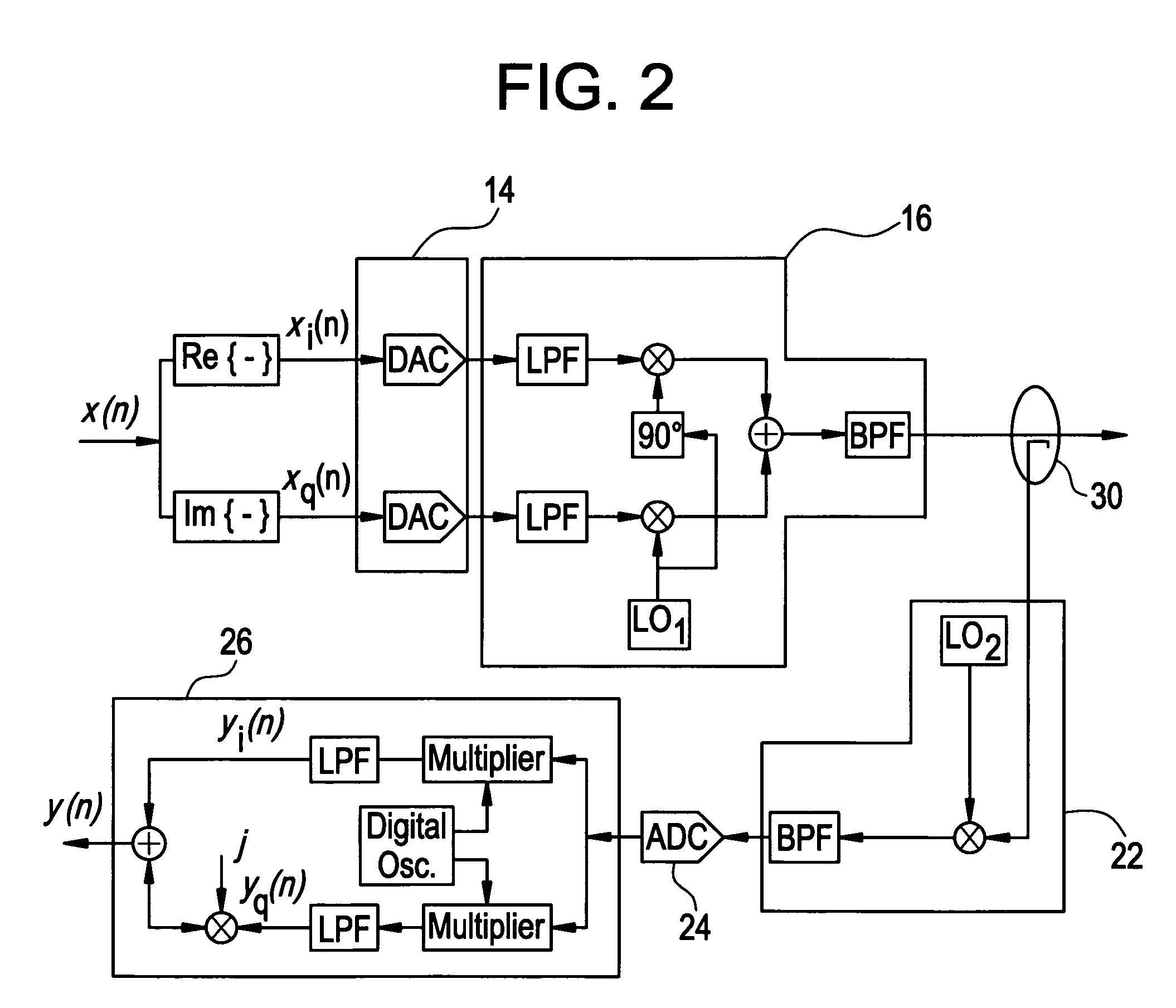
However, in practice, the quadrature carriers in the analog modulator do not have exactly the same amplitudes and an exact phase difference of 90 degrees.
These effects are called gain / phase imbalance and cause cross-talk between the I and Q channels.
If uncompensated, the gain / phase imbalance and the dc offset would have a large effect on predistortion performance.
However, experiments performed by the inventors indicate that the gain / phase imbalance exhibits frequency dependent behavior when the signal bandwidth becomes wide, for example, 15 MHz.

Method used


Image

  • Frequency based modulator compensation
  • Frequency based modulator compensation
  • Frequency based modulator compensation

Examples


Embodiment Construction

[0014]Channel Models

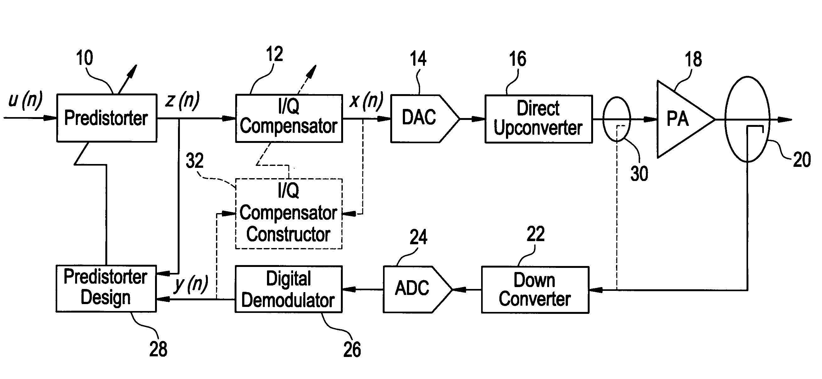
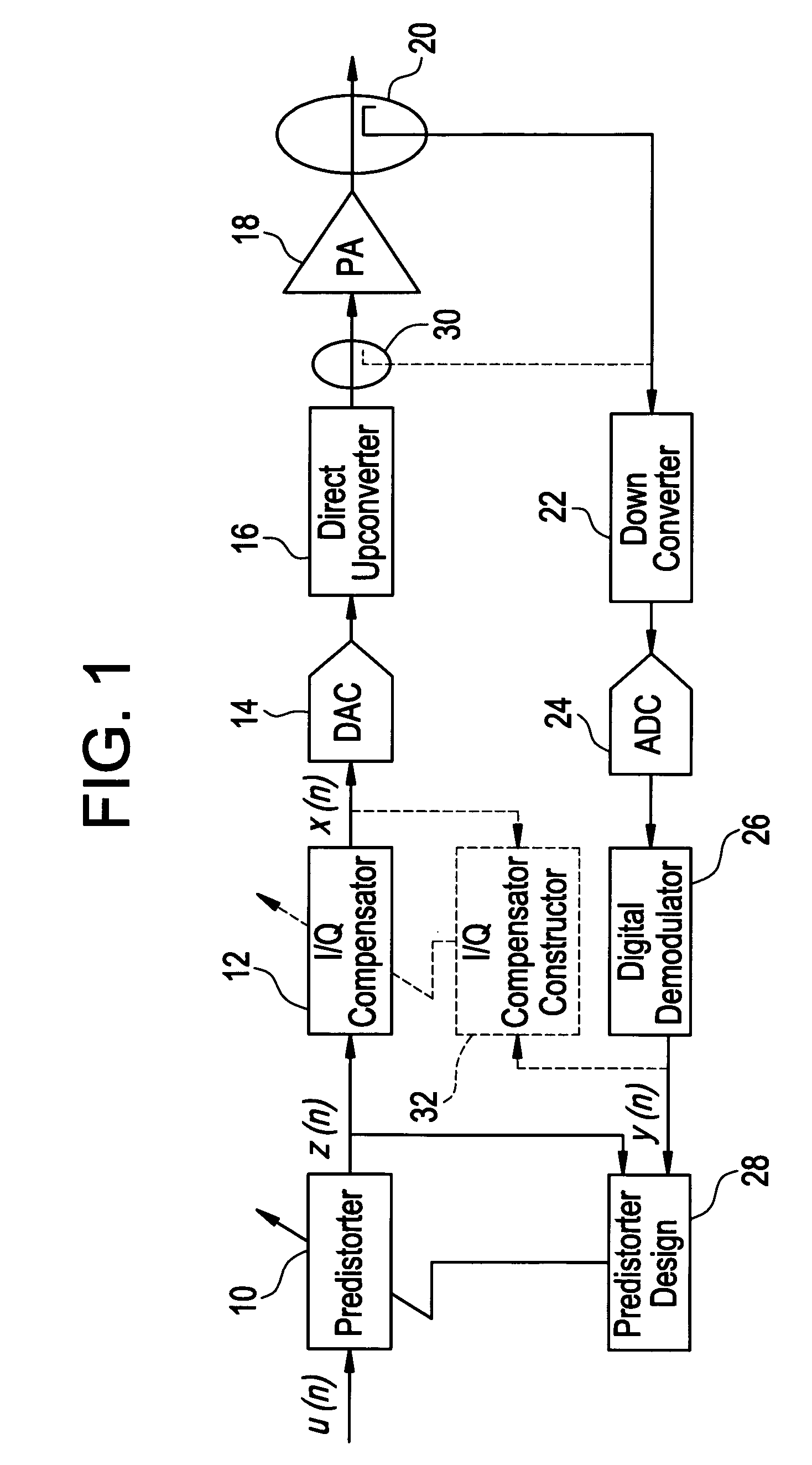
[0015]FIG. 1 illustrates the general structure of transmitter with a baseband predistortion system according to an embodiment of the present invention. As shown, a main signal path includes a predistorter 10, an I / Q compensator 12, a digital-to-analog converter (DAC) 14, a direct upconverter 16 and a power amplifier 18 connected in series. A coupler 20 couples the signal output from the power amplifier 18 to form a feedback path that includes a down converter 22, an analog-to-digital converter (ADC) 24, a digital demodulator 26 and a predistorter design unit 28. As shown in phantom lines, a secondary coupler 30 selectively delivers the output of the direct upconverter 16 to the down converter 22, and an I / Q compensator constructor 32 selectively configures the taps of the I / Q compensator 12. Except for the I / Q compensator 12, secondary coupler 30 and I / Q compensator construction unit 32, the other elements of the baseband predistortion system are well-known in th...


PUM


Abstract

In a transmitter, an upconverter converts a lower frequency signal to a higher frequency signal. Prior to the upconversion, a compensator compensates for at least gain / phase distortion that will be introduced into the lower frequency signal by at least the upconverter.

Description

BACKGROUND OF THE INVENTION[0001]Power amplifiers (PAs) are indispensable components in communication systems and are nonlinear in nature. At the PA output, the nonlinearity not only causes spectral regrowth, which interferes with adjacent channel signals, but also degrades the bit error rate of the inband signal. To compensate for the nonlinearity, PA linearization is often necessary.[0002]Among the linearization techniques, digital baseband predistortion is highly cost effective. It adds a functional block, called a predistorter, before the digital-to-analog conversion and RF upconversion but after any other baseband processing. The predistorter ideally applies the exact inverse response of the power amplifier to a scaled version of the input signal. Therefore, the output of the predistorter-PA cascade is the input signal multiplied by a scaling factor. To construct such a predistorter, a feedback path is needed to capture the output of the PA.[0003]The performance of baseband pre...

Claims


Application Information

Patent Timeline
Patent Type & Authority Patents(United States)
IPC IPC(8): H04K1/02H03C3/40H04B1/04
CPCH03C3/40H04B1/0475H03C2200/0058
Inventor DING, LEIHONCHARENKO, WALTERKERMALLI, MUNAWAR HUSSEINMA, ZHENGXIANGMORGAN, DENNIS RAYMOND
Owner ALCATEL-LUCENT USA INC
Learn More