IP telephone system having a hold function and a callback function
a telephone system and function technology, applied in the field of ip telephone systems having a call holding function and a call back function, can solve the problem that the receiver cannot perform call back
- Summary
- Abstract
- Description
- Claims
- Application Information
AI Technical Summary
Benefits of technology
Problems solved by technology
Method used
Image
Examples
first embodiment
[0029]A first embodiment of the present invention will be explained with reference to FIGS. 1 to 9.
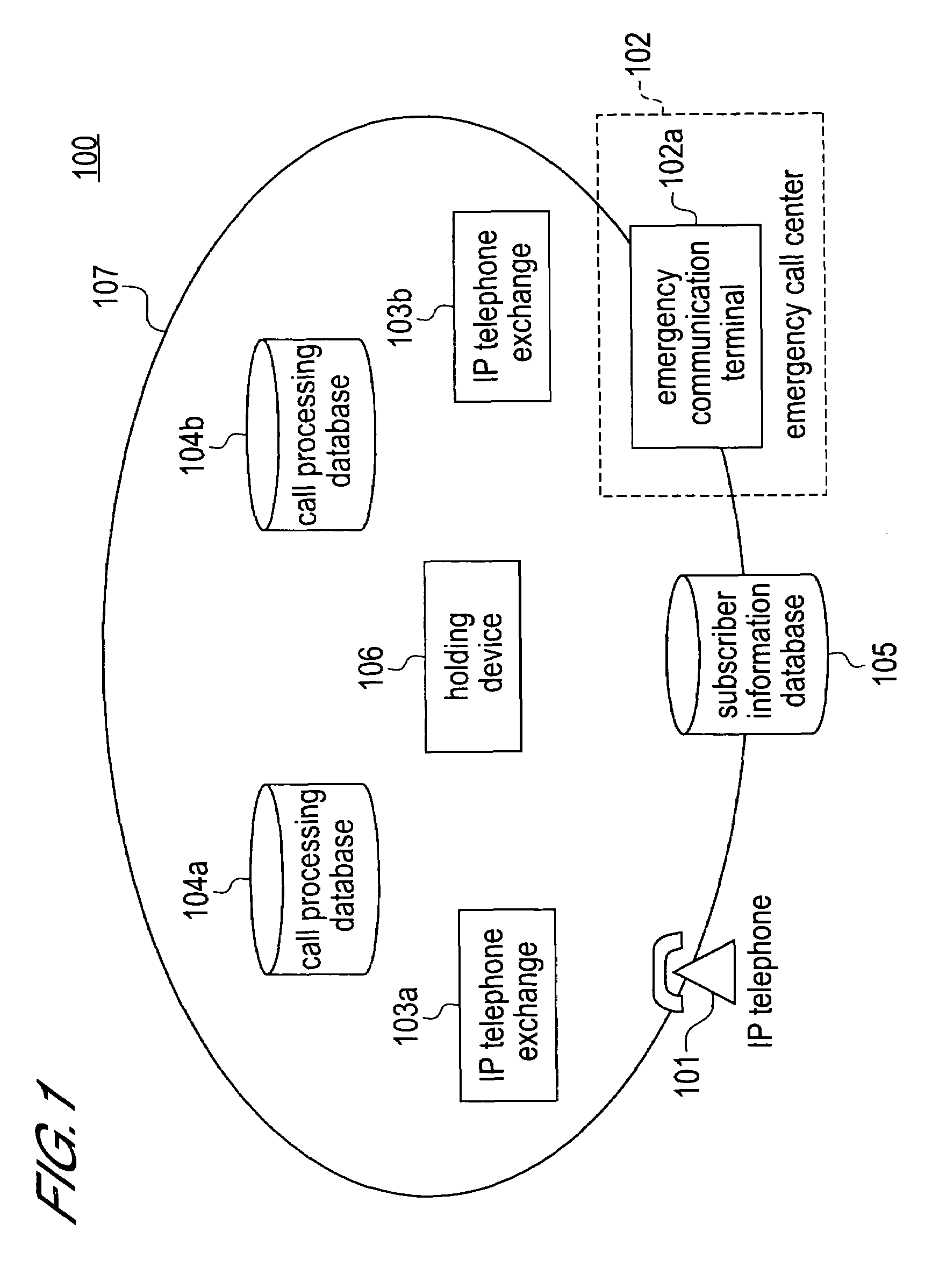
[0030]FIG. 1 is a schematic diagram showing a network structure of an IP telephone system 100 according to the first embodiment.
[0031]As described in FIG. 1, the IP telephone system 100 includes an IP telephone terminal 101, an emergency call center 102, IP telephone exchanges 103a and 103b, call processing databases 104a and 104b, a subscriber information database 105, a holding device 106 and a VoIP network 107.
[0032]The IP telephone terminal 101 is a telephone terminal for a subscriber to use the IP telephone services. The type of the IP telephone terminal is not limited in the present embodiment. The IP telephone terminal may be configured to be, for example, a normal telephone set connected to a terminal adapter for the IP telephone services, or a personal computer connected to a terminal adapter for the IP telephone services. In FIG. 1, the single IP telephone terminal 101 is exp...
second embodiment
[0126]A second embodiment of the present invention will be explained with reference to FIGS. 10 to 13.
[0127]A system structure and functions of an IP telephone system according to the present embodiment are the same as those of the system according to the first embodiment. The present embodiment differs from the first embodiment on the point that the holding device which is used is determined when an emergency call is connected.
[0128]FIG. 10 is a schematic diagram showing sequence of an operation regarding an emergency call function of the present embodiment. In FIG. 10, the processes of the steps referred by same step numbers as those of in FIG. 5 are the same processes in the case of FIG. 5.
[0129]The processes of steps S112 to S115 are the same as in the case of the first embodiment (See FIG. 5). Firstly, the IP telephone terminal 101 transmits a call request notification to the IP telephone exchange 103a (See step S112 in FIG. 10). The IP telephone exchange 103a which receives th...
third embodiment
[0152]A third embodiment of the present invention will be explained with reference to FIGS. 14 to 20.
[0153]The present embodiment is different from the first embodiment on the point that the system of the present embodiment comprises a function to remain the connection when an IP telephone terminal in a hold state is moved (that is a case where an IP telephone exchange which manages an IP telephone terminal 101 is switched).
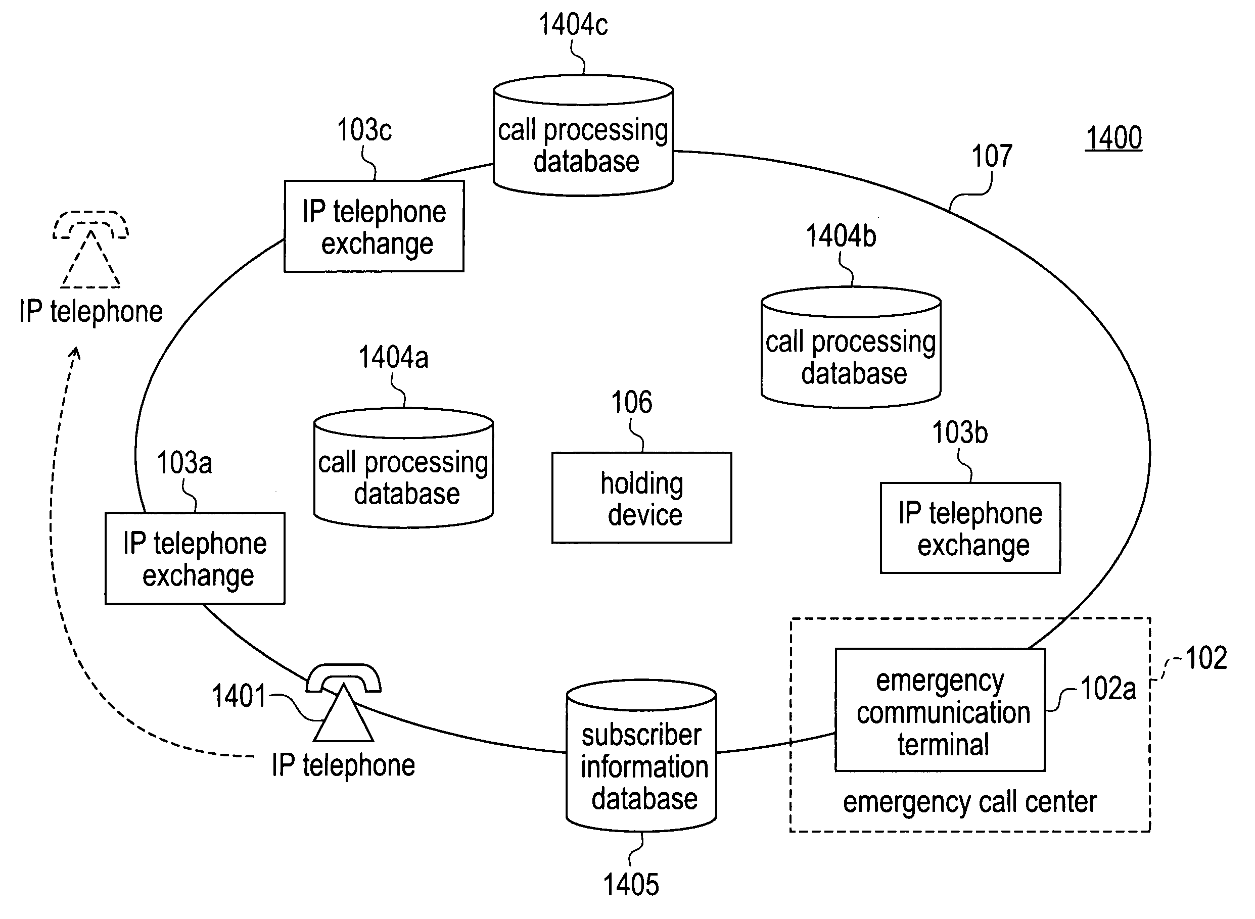
[0154]FIG. 14 is a schematic diagram showing a network structure of an IP telephone system 1400 according to the present embodiment. In FIG. 14, the elements referred by same numbers as those of in FIG. 1 are the same element in the case of FIG. 1.
[0155]As shown in FIG. 14, the IP telephone system 1400 includes an IP telephone terminal 1401, an IP telephone exchange 103c, call processing databases 1404a, 1404b, 1404c, a subscriber information database 1405.
[0156]The IP telephone terminal 1401 is a mobile type IP telephone set, for example a mobile computer with a...
PUM
 Abstract
Description
Claims
Application Information
 - R&D
- Intellectual Property
- Life Sciences
- Materials
- Tech Scout
- Unparalleled Data Quality
- Higher Quality Content
- 60% Fewer Hallucinations
Browse by: Latest US Patents, China's latest patents, Technical Efficacy Thesaurus, Application Domain, Technology Topic, Popular Technical Reports.
© 2025 PatSnap. All rights reserved.Legal|Privacy policy|Modern Slavery Act Transparency Statement|Sitemap|About US| Contact US: help@patsnap.com


