
Transcatheter delivery of a replacement heart valve

a heart valve and transcatheter technology, applied in the field of treatment of heart valve dysfunction, can solve the problems of pulmonary valve regurgitation, heart valve dysfunction, subsequent leaking of blood, etc., and achieve the effect of avoiding the morbidity of reoperation and being minimally invasiv

Active Publication Date: 2008-12-30
CHILDRENS MEDICAL CENT CORP
View PDF21 Cites 281 Cited by
  • Summary
  • Abstract
  • Description
  • Claims
  • Application Information

AI Technical Summary

Benefits of technology

Enables minimally invasive heart valve replacement reducing morbidity, allowing for smaller catheter sizes, precise alignment, and potential for multiple valve frame replacements without reoperation, thereby reducing surgical risks and recovery time.

Problems solved by technology

Postoperative complications that may appear during short and long-term patient follow-up include heart valve dysfunction.
The surgical procedure typically results in subsequent leaking (i.e., regurgitation) of blood through the pulmonary valve.
Over the life of the patient, the regurgitation may become more severe and result in further dysfunction of the heart valve due to, for example, dilation of the heart chamber and heart valve, by the body, to compensate for the increased regurgitation.
This surgery is very expensive and requires a prolonged recovery period in the hospital with additional rehabilitation once the patient is discharged.
This invasive surgery also results in a large chest scar.
The dysfunction of this heart valve leads to a volume load on the right ventricle and causes right ventricular dilation, which can lead to right ventricular dysfunction which is thought to contribute to ventricular tachycardia and sudden death.
Cardiologists typically defer the valve replacement procedure as long as possible, because of: the need for a repeat open-heart surgery; the risks of surgery and cardiopulmonary bypass; and the limited lifespan of all available surgically-implanted valves.
The risks associated with surgical valve replacement are particularly acute with respect to pediatric patients in that the replacement valves do not grow with the patient and thus require more frequent replacement.
Valve replacement surgery is thus very demanding on the patient's body and may, therefore, not be a viable technique for patients that are physically weak due to age or illness.

Method used


Image

  • Transcatheter delivery of a replacement heart valve
  • Transcatheter delivery of a replacement heart valve
  • Transcatheter delivery of a replacement heart valve

Examples


Embodiment Construction

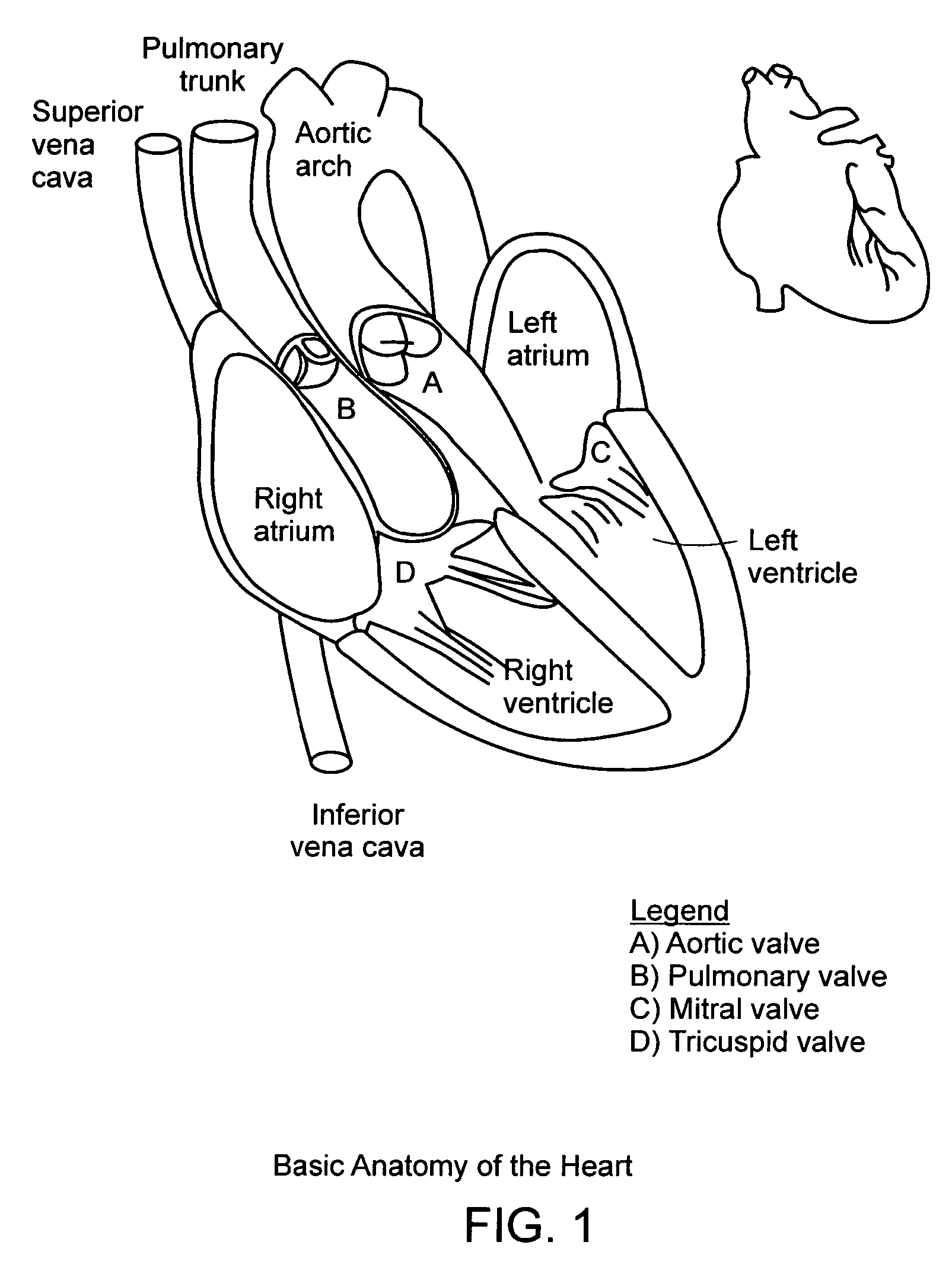
[0063]In brief overview and with reference to FIG. 1, the heart has four chambers and is located in the middle of the chest with a slight tilt toward the left side. Deoxygenated blood (containing low oxygen) returns from the entire body via the superior and inferior branches of the vena cava emptying into the right atrium. During diastole, or the relaxation phase of the cardiac cycle, pressure in the right ventricle falls from between about 20 mm Hg and about 30 mm Hg to between about 5 mm Hg and about 10 mm Hg. The pressure gradient formed between the right atrium and right ventricle, plus the contraction of the atrium, causes forward flow of blood through the tricuspid valve into the right ventricle. The flow of blood through the tricuspid valve thereby fills the right ventricle with blood. During systole, the pumping phase of the cycle, the right ventricle starts to contract, increasing intraventricular pressure. This causes the tricuspid valve to snap shut and the cusps of the p...


PUM


Abstract

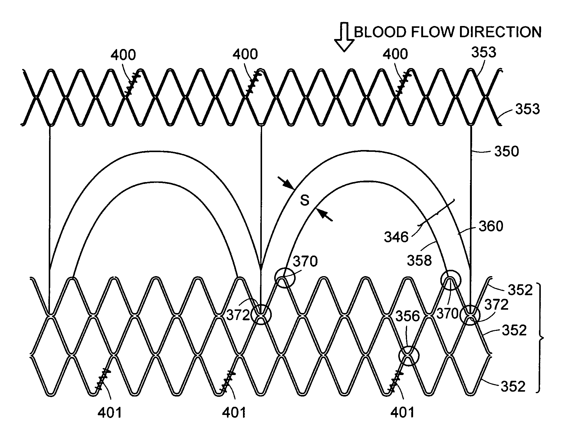
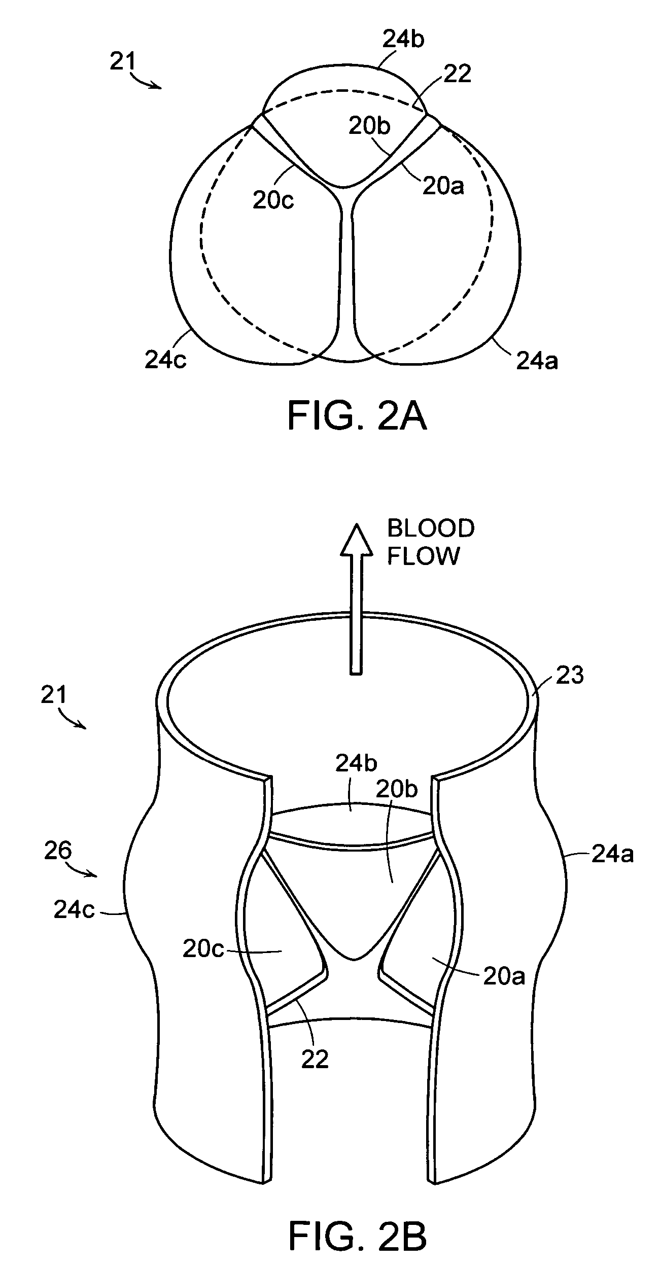
A replacement heart valve apparatus. The heart valve apparatus includes a stent and a valve frame having a substantially cylindrical body defining a lumen. The valve frame includes a plurality of curved wire pairs attached to the substantially cylindrical body. Each curved wire pair includes an inner curved wire and an outer curved wire. The wire frame further having a plurality of leaflets. Each leaflet is attached to a respective inner curved wire and extends over a respective outer curved wire, so as to position the body of the leaflet within the lumen of the valve frame.

Description

RELATED APPLICATIONS[0001]This application claims the benefit of and priority to U.S. Provisional Application Ser. Nos. 60 / 542,008, filed on Feb. 5, 2004; 60 / 575,167, filed on May 28, 2004; and 60 / 610,271, filed on Sep. 16, 2004, and owned by the assignee of the present application, the entire contents of which are herein incorporated by reference.TECHNICAL FIELD[0002]The present technology relates generally to the treatment of heart valve dysfunction and, in particular, to minimally invasive systems and methods for replacing such heart valves.BACKGROUND IF THE INVENTION[0003]Treatment of congenital heart disease typically requires surgical intervention, such as “open-heart” surgery during which the thoracic cavity is opened and the heart, arteries / veins and / or associated valves are repaired or otherwise treated. Postoperative complications that may appear during short and long-term patient follow-up include heart valve dysfunction. For example, tetrology of fallot is a congenital h...

Claims


Application Information

Patent Timeline
Patent Type & Authority Patents(United States)
IPC IPC(8): A61F2/24A61F2/06A61F2/90
CPCA61F2/2412A61F2/2418A61F2/2433A61F2/2436A61F2230/0054A61F2250/0002A61F2250/0067A61F2220/0008A61F2220/0016A61F2/91
Inventor NUGENT, ALANLOCK, JAMES E.
Owner CHILDRENS MEDICAL CENT CORP
Learn More