
Portable power system

a power system and portable technology, applied in the direction of wind motors with solar radiation, machines/engines, propulsion parts, etc., can solve the problems of prior art not addressing the need for portable, continuous, reliable, renewable energy power,

Inactive Publication Date: 2008-12-30
SACRED POWER CORP
View PDF32 Cites 110 Cited by
  • Summary
  • Abstract
  • Description
  • Claims
  • Application Information

AI Technical Summary

Benefits of technology

[0022]A primary advantage of the present invention is that it is provides continuous, uninterrupted energy to remote sites immediately upon delivery.

Problems solved by technology

However, the invention does not provide for portability and uses only wind energy that may be stored as compressed air.
The prior art does not address the need to provide portable, continuous, reliable, and renewable energy power—particularly to remote sites.

Method used


Image

  • Portable power system
  • Portable power system
  • Portable power system

Examples


example

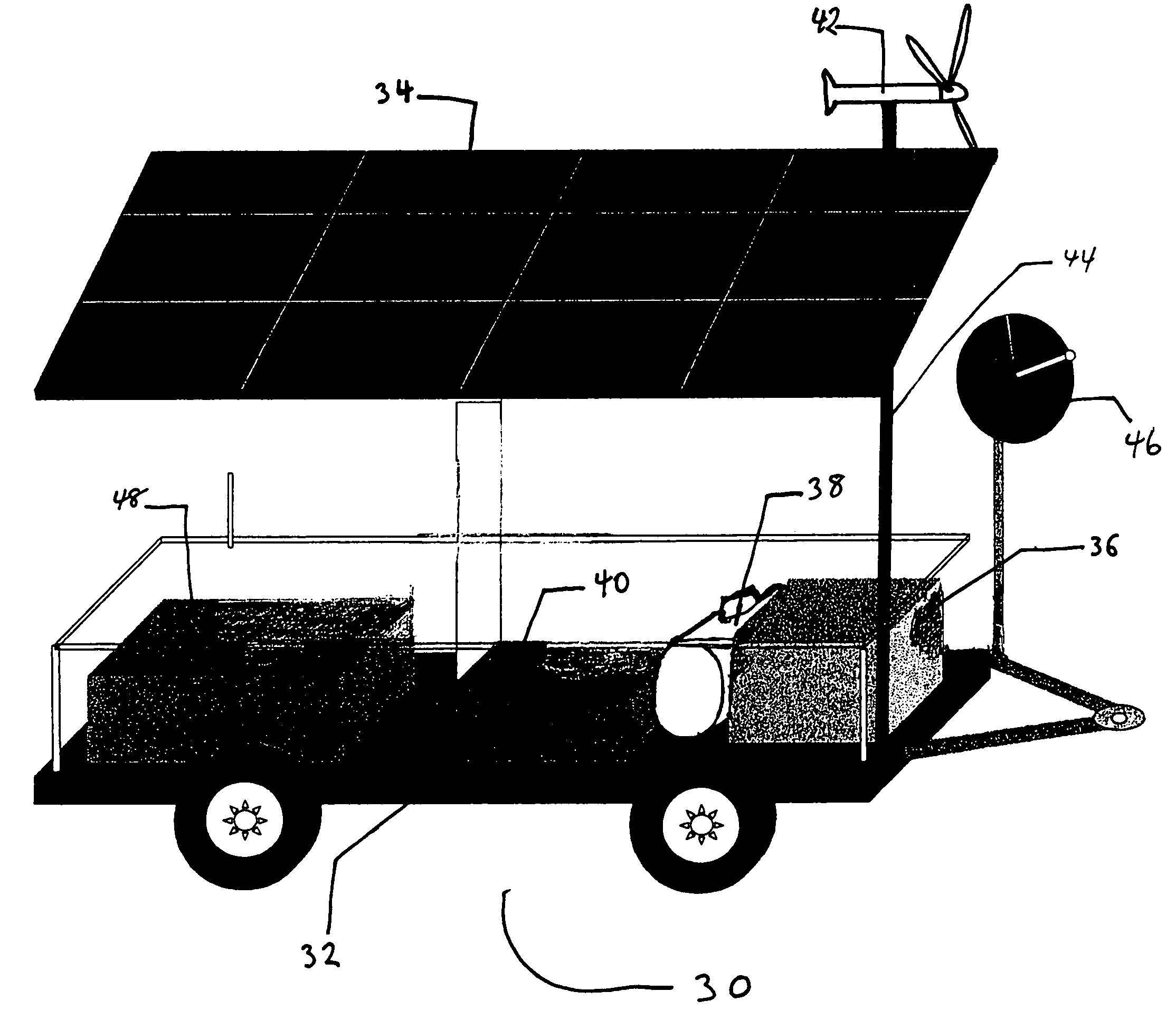
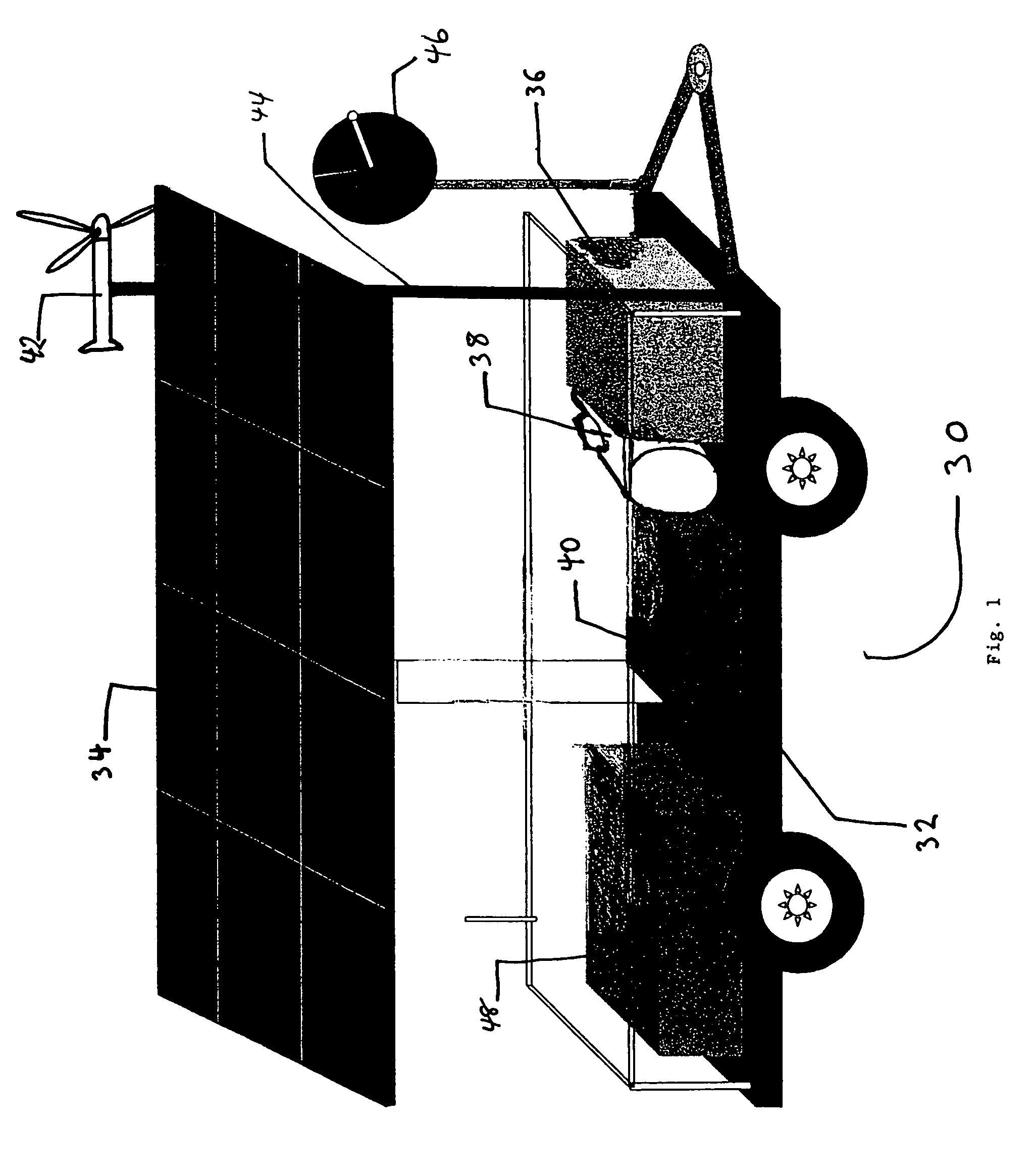
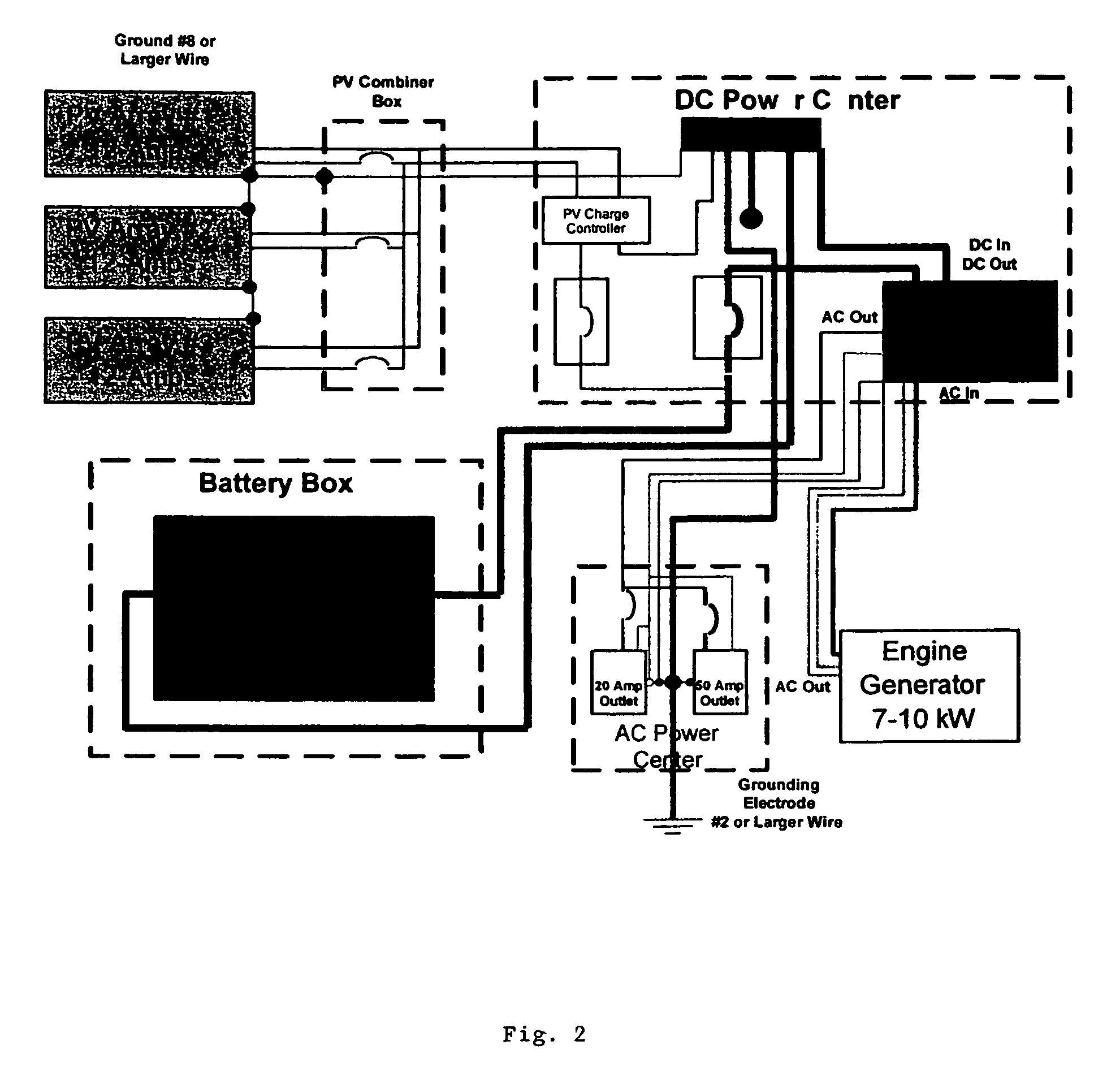
[0038]A remote assembly was constructed in accordance with the present invention. There was included a 1200 watt photovoltaic solar array (manufactured by Matrix Photovoltaics) mounted on a motorized tracking system (manufactured by Array Technologies) that increased the power producing by 38% than a fixed array. A “Cool-Cell” battery box (manufactured by Zomeworks of Albuquerque, N. Mex.) housed eight gel-cell, maintenance free batteries. A 12,000 watt propane-powered generator was mounted on the platform, along with a 120-gallon tank, which is enough for 30 days of two hours / day operation. A 1000 watt Bergey XL.1 wind turbine on a 30-foot tower was also mounted on the platform. The platform was made of steel frame. The system had a continuous power output rating of 2.5 kw / hour. The dimensions were: length (14.5 feet), width (5.5 feet), height (12.5 feet), and weight (4000 lbs.). The assembly included satellite communications (both telephone and Internet). A larger power conditioni...


PUM


Abstract

A remote and portable, hybrid power system comprising one or more of the following components: a solar system, batteries, a back-up generator, a wind energy system, and a communications system. The components are disposed on a platform that is portable and transportable to the remote location by a truck or other transportation vehicle.

Description

[0001]This application claims the benefit of the filing of U.S. Provisional Patent Application Ser. No. 60 / 430,215, entitled “Remote Power System”, filed on Dec. 2, 2002, and the specification thereof is incorporated herein by reference.BACKGROUND OF THE INVENTION[0002]1. Field of the Invention (Technical Field)[0003]The present invention relates to a portable, hybrid power assembly comprising one or more of the following components: a solar energy power system, batteries, a back-up generator, and a wind energy system. These components are constructed on a platform that is transportable to a location, including remote locations, by a truck or other transportation vehicle that travels by land, water, or air.[0004]2. Description of Related Art[0005]Note that the following discussion refers to a number of publications by author(s) and year of publication, and that due to recent publication dates certain publications are not to be considered as prior art vis-a-vis the present invention....

Claims


Application Information

Patent Timeline
IPC IPC(8): F01K27/00
CPCF03D9/007F03D9/021F03D11/04F03G6/001H02S20/00H02S10/10F05B2240/923F05B2240/931Y02T90/16Y02E10/465Y02E10/50Y02E10/727B60L2200/28F05B2240/941F03D9/11F03D13/20H02S20/32H02S10/40Y02E10/46B60K16/00F03D9/25F03D9/32H02S10/12Y02E10/72Y02E70/30
Inventor MELTON, DAVID S.ARMIJO-CASTER, ODES
Owner SACRED POWER CORP
Learn More