
Strengthened optical waveguide fiber cable

a fiber cable and fiber technology, applied in the field ofloose tube optical waveguide fiber cables, can solve the problems of time-consuming and time-consuming process of accessing the fibers, tight buffered fibers, and the cost of central filling loose tubes, and achieve the effect of reducing the access time of the fibers

Active Publication Date: 2008-12-23
DRAKA COMTEQ BV
View PDF13 Cites 5 Cited by
  • Summary
  • Abstract
  • Description
  • Claims
  • Application Information

AI Technical Summary

Benefits of technology

The present invention provides a loose tube optical waveguide fiber cable that is cost-effective for large-scale installation of fiber-to-the-home (FTTH) and has a reduced fiber access time compared to standard cable elements. The cable includes two or more optical waveguides, a protective tube loosely surrounding the waveguides, and one or more strengthening members disposed between the inner surface of the protective tube and the outer surface of the protective tube. The strengthening members include either one or more longitudinally embedded strengthening elements or a longitudinal layer of material that serves as a strengthening element, and extend continuously along the length of the protective tube.

Problems solved by technology

One disadvantage of the optical fiber cables according to the prior art is that the tight buffered fibers and the central filled loose tubes are expensive.
Moreover, accessing the fibers is a time consuming process, and especially when a gel-filled, central loose tube is used, fiber cleaning is necessary.

Method used


Image

  • Strengthened optical waveguide fiber cable
  • Strengthened optical waveguide fiber cable

Examples


Embodiment Construction

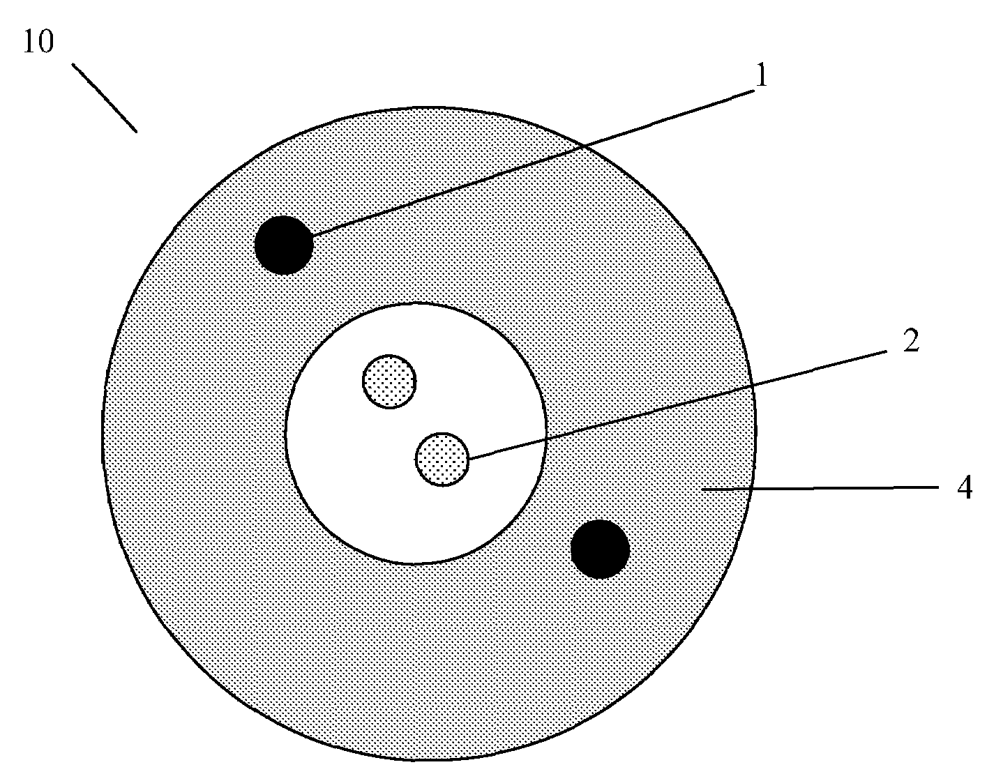
[0017]A loose tube optical waveguide fiber cable 10 may be constructed as shown in FIGS. 1 and 2. Cable 10 contains two optical fibers 2 surrounded by a coating (not shown) applied directly over the optical fiber 2. The number of optical fibers 2 is not restricted to two (i.e., more than two may be used). There are no filling gels, swellable materials, or the like present in the space between the optical fibers 2 and the inner surface of the protective tube 4. The optical fiber 2 may be composed of a core and a cladding surrounding the core, with one or more polymer coatings applied over the cladding. A protective tube 4 loosely surrounds the optical fibers 2.

[0018]The cable 10 has strengthening elements 1 that are relatively flexible and that have high traction strength. The strengthening elements 1 are embedded in the sheath 4 parallel to the axis of the cable 10 (i.e., between the inner surface of the protective tube 4 and the outer surface of protective tube 4). These strengthen...


PUM


Abstract

The present invention relates to a loose tube optical waveguide fiber cable that is suitable for riser or plenum applications. The cable includes a protective tube that loosely surrounds two or more optical waveguides inside the hollow cavity defined by the tube. The protective tube has an inner surface and an outer surface and is a dry structure. Accordingly, the protective tube does not contain any gel-like compounds or other materials around the optical fibers positioned inside the protective tube. Strengthening members are disposed between the inner surface of the protective tube and the outer surface of the protective tube. The strengthening members are configured as embedded or layered strengthening elements and are disposed longitudinally along the length of the cable.

Description

CROSS-REFERENCE TO PRIORITY APPLICATION[0001]This application claims the benefit of pending International Application No. PCT / NL2006 / 000439 (filed Aug. 31, 2006, under the Patent Cooperation Treaty at the Dutch Patent Office), via 35 U.S.C. §365(a). International Application No. PCT / NL2006 / 000439 is hereby incorporated by reference in its entirety.FIELD OF THE INVENTION[0002]The present invention relates to loose tube optical waveguide fiber cables suitable for riser or plenum applications.BACKGROUND OF THE INVENTION[0003]Optical waveguide fibers are normally provided with a plastic protective coating applied by the fiber manufacturer directly over the cladding to protect the fiber.[0004]In tight buffered cables, a protective tube is applied by the cable manufacturer directly to the outer surface of the fiber coating so that the fiber and the tube are in contact substantially along their lengths. In loose tube or composite buffer constructions, the coated optical fiber is separated ...

Claims


Application Information

Patent Timeline
Patent Type & Authority Patents(United States)
IPC IPC(8): G02B6/44
CPCG02B6/4432G02B6/4436
Inventor NOTHOFER, KLAUSLAUSCH, PETER
Owner DRAKA COMTEQ BV
Learn More