
Radio frequency power amplifier

a power amplifier and frequency technology, applied in the direction of amplifier combinations, rf amplifiers, multi-port networks, etc., can solve the problems of increased sensitivity of output power with respect to the base voltage, difficult control of output power, etc., to reduce the power load efficiency of non-linear transistors and suppress the effect of adjusting output voltag

Inactive Publication Date: 2008-12-23
COLLABO INNOVATIONS INC
View PDF4 Cites 6 Cited by
  • Summary
  • Abstract
  • Description
  • Claims
  • Application Information

AI Technical Summary

Benefits of technology

"The present invention is about a radio frequency power amplifier that can adjust the output power while maintaining efficiency. It includes a former-stage transistor, a latter-stage transistor, and an inter-stage matching circuit. The inter-stage matching circuit has a high-pass filter circuit and an impedance conversion device with which a phase shift of a second harmonic signal is 15 degrees or greater. This design helps to suppress the reduction in power load efficiency of the non-linear transistor and adjust the output voltage effectively."

Problems solved by technology

Therefore, the sensitivity of the output power with respect to the base voltage is increased, which makes it difficult to control the output power.

Method used


Image

  • Radio frequency power amplifier
  • Radio frequency power amplifier
  • Radio frequency power amplifier

Examples


Embodiment Construction

[0037]Hereinafter, embodiments of the present invention will be described with reference to the drawings.

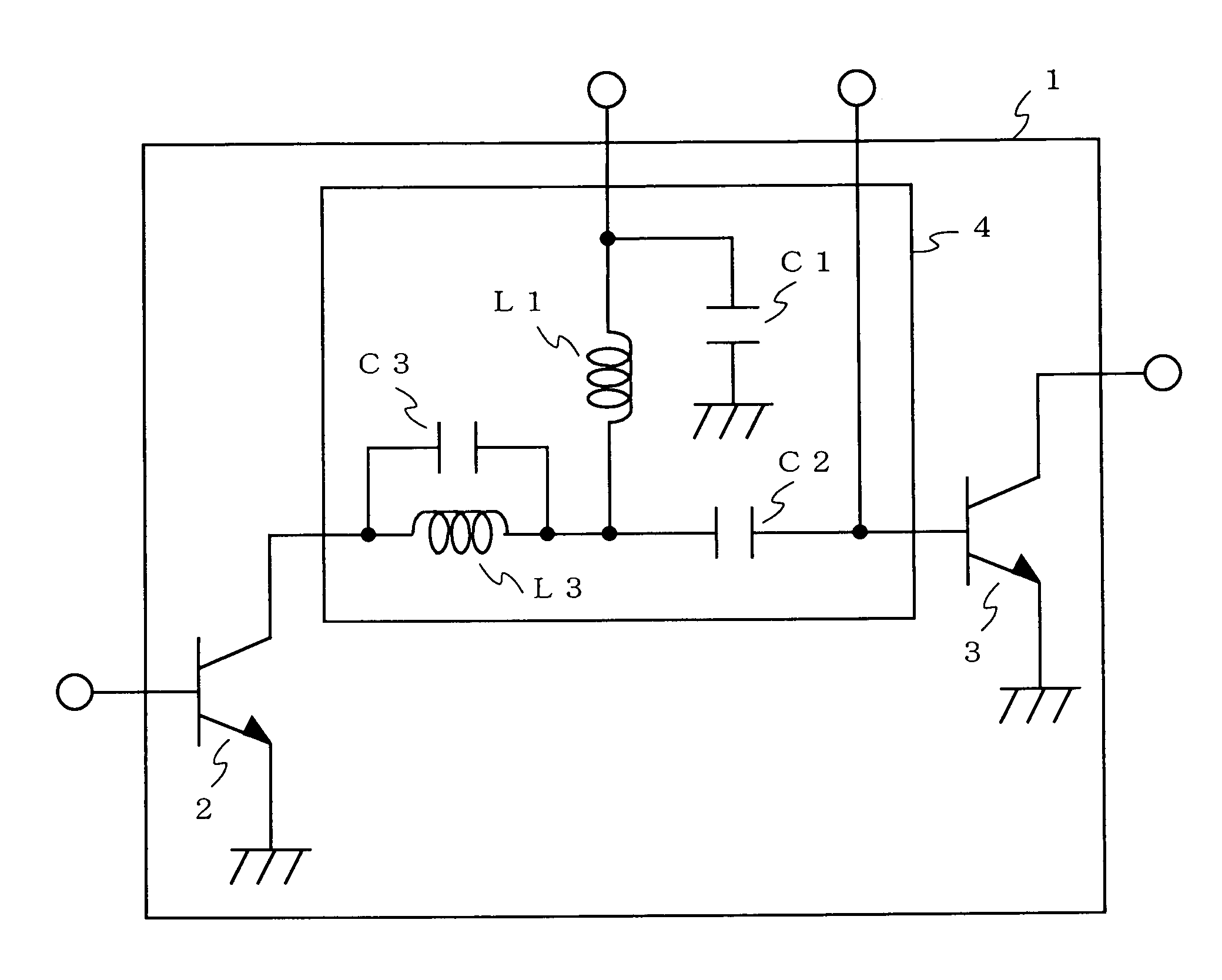
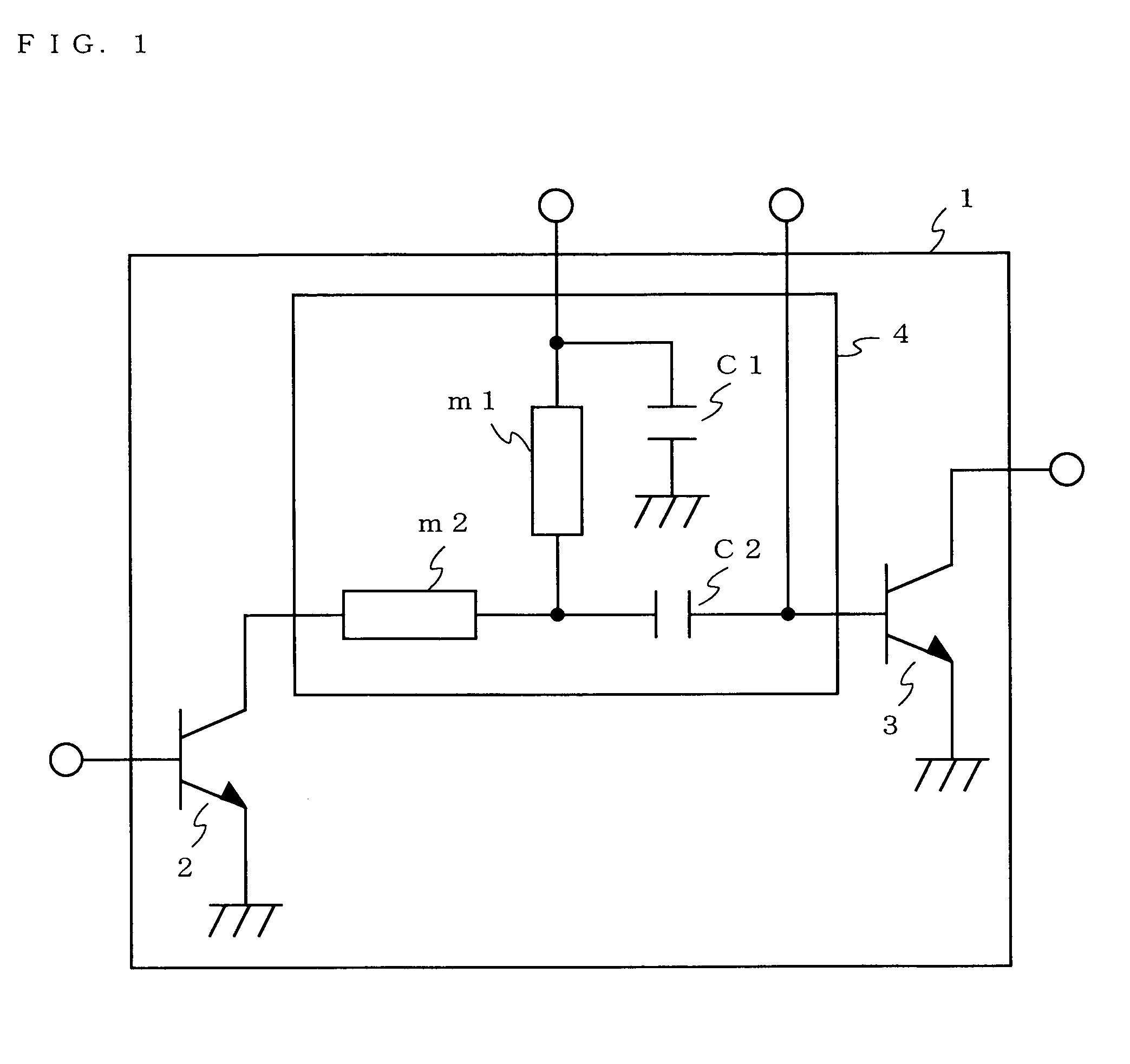
[0038]FIG. 1 shows a schematic configuration of a radio frequency power amplifier 1 according to one embodiment of the present invention. As shown in FIG. 1, the radio frequency power amplifier 1 in this embodiment includes a former-stage transistor 2, a latter-stage transistor 3, and an inter-stage matching circuit 4 for connecting the former-stagetransistor2 and the latter-stage transistor 3. The inter-stage matching circuit 4 is a high-pass filter type circuit, and includes transmission lines m1 and m2, and capacitors C1 and C2.

[0039]In the former-stage transistor 2, a radio frequency signal is input to a base, and an amplified radio frequency signal is output from a collector. An emitter of the former-stage transistor 2 is grounded. The post-amplification radio frequency signal which is output from the collector of the former-stage transistor 2 is input to a base of the latte...


PUM


Abstract

A radio frequency power amplifier 1 includes a former-stage transistor 2, a latter-stage transistor 3, and an inter-stage matching circuit 4 for connecting the former-stage transistor 2 and the latter-stage transistor 3. The inter-stage matching circuit 4 includes a high-pass filter circuit including a transfer line m1, a capacitor C1 and a capacitor C2; and a transfer line m2 with which a passage phase of a secondary harmonic signal is 15 degrees or greater.

Description

BACKGROUND OF THE INVENTION[0001]1. Field of the Invention[0002]The present invention relates to a radio frequency power amplifier suitable for power amplification of a radio frequency signal, which includes a plurality of stages of transistors.[0003]2. Description of the Background Art[0004]A radio frequency power amplifier used for wireless communication is desired to be designed to have a low distortion and a high efficiency. In many communication systems, a quadrature modulation system is used to improve the communication speed, and a communication signal is processed with amplitude modulation in addition to phase modulation in order to suppress frequency dispersion of the modulated signal. Therefore, as a radio frequency power amplifier, a linear amplifier capable of reproducing the amplitude modulation performed on an input signal with high fidelity is used.[0005]In the GMSK (Gaussian filtered Minimum Shift Keying) modulation used for GSM (Global System for Mobile Communicatio...

Claims


Application Information

Patent Timeline
Patent Type & Authority Patents(United States)
IPC IPC(8): H03F3/191
CPCH03F1/0261H03F1/56H03F3/602H03H7/383H03F2200/15H03F2200/168H03F2200/18H03F2200/318H03F2200/411H03F2200/451H03F2200/543H03F2200/75
Inventor MATSUDA, SHINGOTATEOKA, KAZUKIMAKIHARA, HIROKAZU
Owner COLLABO INNOVATIONS INC
Learn More