
Lightweight protector against micrometeoroids and orbital debris (MMOD) impact using foam substances

a technology of micrometeoroids and orbital debris, applied in the direction of protective clothing, building components, armour, etc., can solve the problems of significant weight penalty on a protected structure, significant temperature drop on the outer surface of the shield, and serious damage to an unprotected spacecraft. , to achieve the effect of light weigh

Active Publication Date: 2008-12-16
THE BOEING CO
View PDF8 Cites 5 Cited by
  • Summary
  • Abstract
  • Description
  • Claims
  • Application Information

AI Technical Summary

Benefits of technology

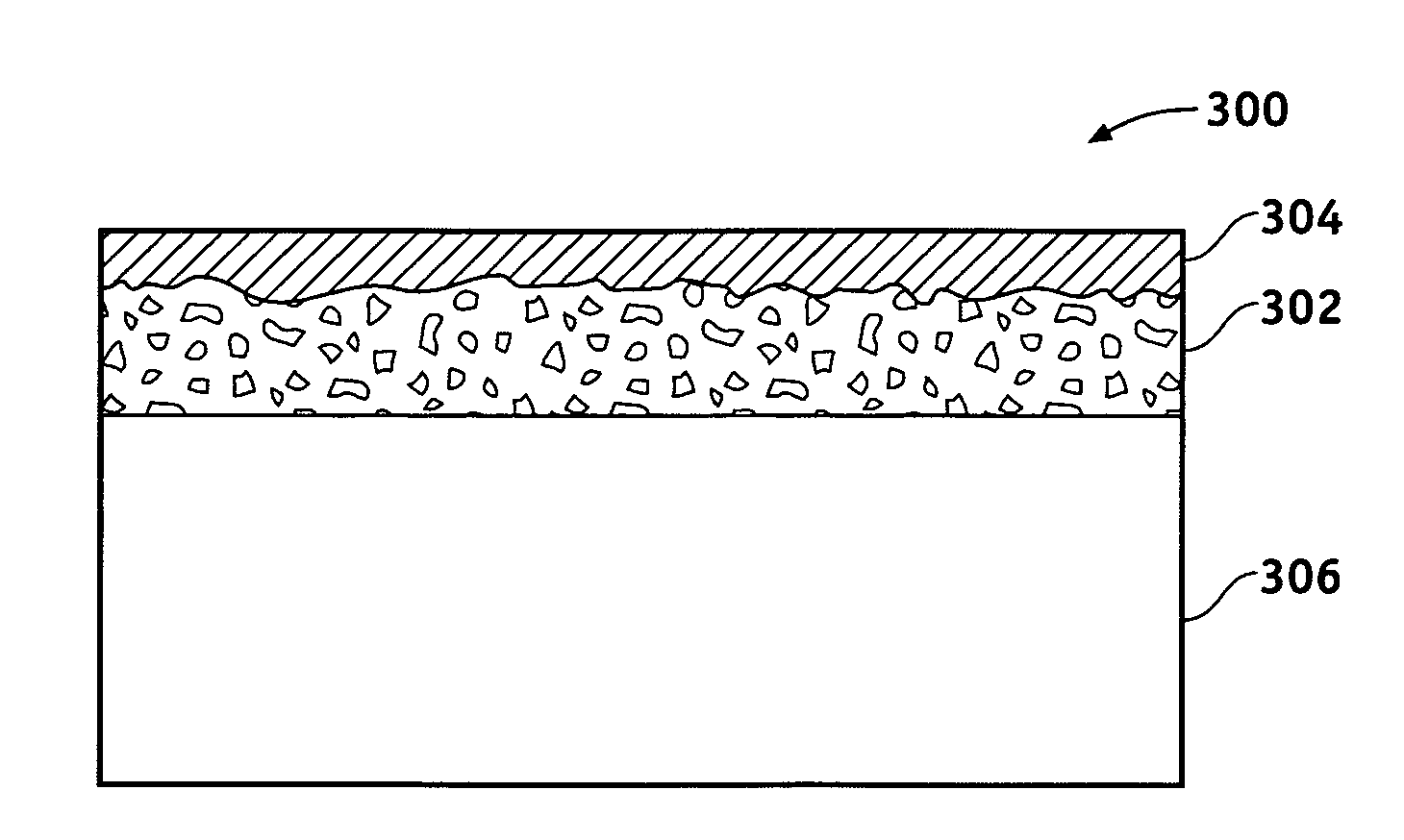
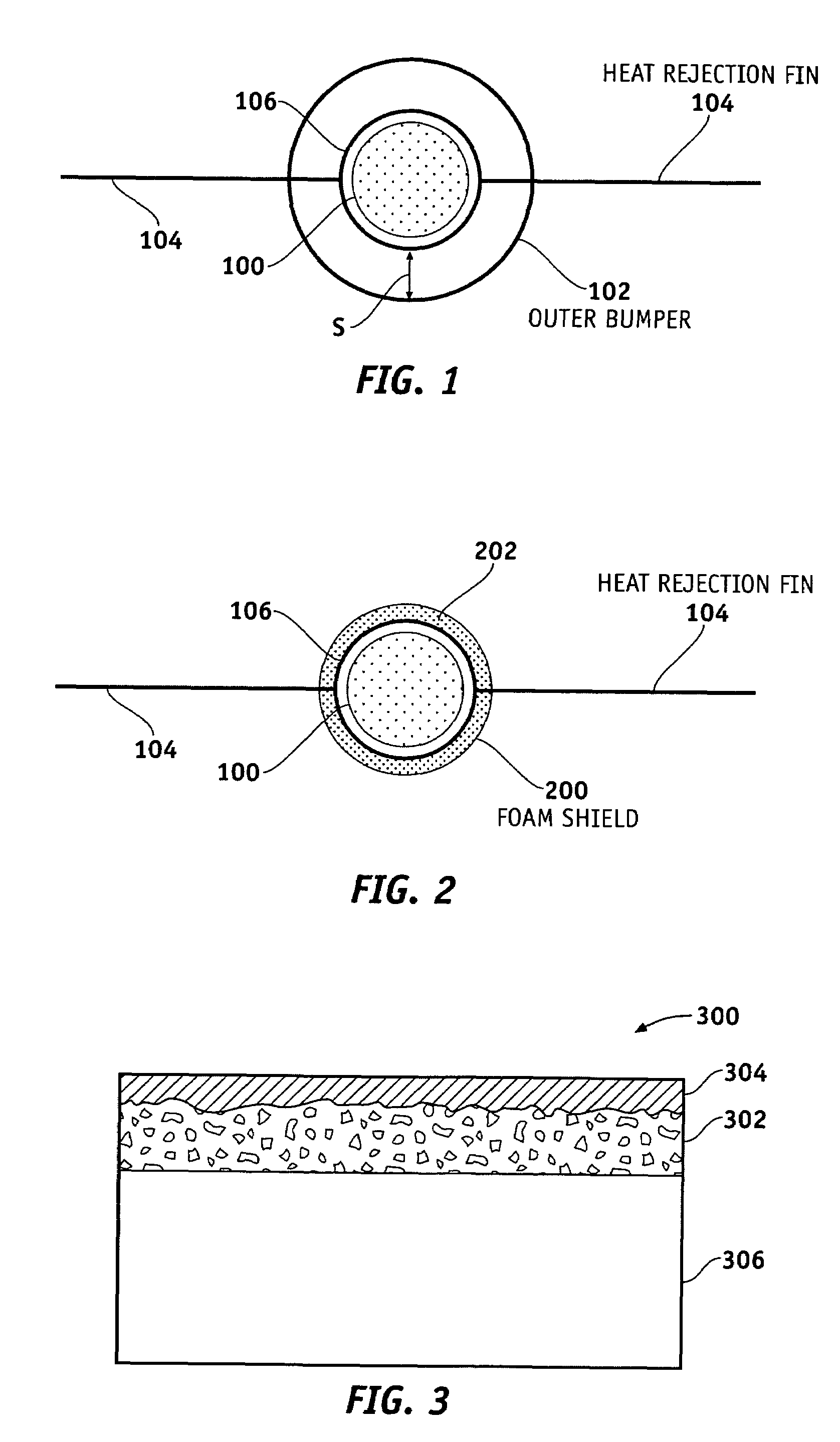
The patent describes a device and method for protecting surfaces from high-velocity projectiles such as MMOD. The device consists of a foam material that is attached directly to the surface and a coating material that penetrates the foam to a certain depth. The foam can be made of metal, ceramic, or a composite, and the coating material can be metal plating, Chemical Vapor Deposition, or Physical Vapor Deposition. The foam is typically attached to the surface using brazing or adhesive bonding. The foam and coating materials can be adjusted to have specific sonic velocity, toughness, and thermal conductivity values, making it significantly lighter than conventional shields with equivalent protective characteristics.

Problems solved by technology

One of the many design challenges in the field of spacecraft technology involves the protection of the spacecraft (e.g., communications satellites, space stations, etc.) from impact with micrometeoroids and orbital debris (MMOD).
), and can cause serious damage to an unprotected spacecraft.
All-aluminum or Whipple types of protective shields, however, can impose a significant weight penalty on a protected structure, which is generally undesirable in a spacecraft application.
In addition, the standoff distance of a Whipple shield typically becomes a vacuum space during a spacecraft mission, and when disposed on heat dissipation surfaces, can significantly lower the temperature on the outer surface of the shield.

Method used


Image

  • Lightweight protector against micrometeoroids and orbital debris (MMOD) impact using foam substances
  • Lightweight protector against micrometeoroids and orbital debris (MMOD) impact using foam substances

Examples


Embodiment Construction

[0012]The following detailed description is merely exemplary in nature and is not intended to limit the invention or the application and uses of the invention. Furthermore, there is no intention to be bound by any expressed or implied theory presented in the preceding technical field, background, brief summary or the following detailed description.

[0013]Various embodiments of the present invention pertain to the area of protecting a device such as a spacecraft from the impact of MMOD. To overcome the disadvantages of conventional protective shields with respect to weight and heat dissipation, exemplary embodiments of protective shields are configured with lightweight foam materials such as metal, ceramic, or organic. The porous structure of the foam material can enable diffusion of an impact shock and debris, and the specific configuration of the foam shield can be tailored to optimize heat dissipation characteristics.

[0014]As noted in the Background, conventional multi-layer metal ...


PUM

PropertyMeasurementUnit
porosityaaaaaaaaaa
depthaaaaaaaaaa
hyper-velocityaaaaaaaaaa

Abstract

Methods and apparatus are provided for a shield to protect a surface from the impact of hyper-velocity projectiles. The apparatus comprises a foam material that is configured to cover the surface to be protected and is attached directly to that surface. A coating material is typically disposed on the outer surface of the foam material and may penetrate the foam material to a predetermined depth. The foam material and the coating material are selected to form a composite having predetermined values of sonic velocity, toughness, and thermal conductivity. The composite of foam material and coating material can be significantly lighter in weight than a metal shield having equivalent protective characteristics.

Description

TECHNICAL FIELD[0001]The present invention generally relates to mechanical shield devices, and more particularly relates to lightweight protectors for spacecraft against micrometeoroids and orbital debris (MMOD).BACKGROUND[0002]One of the many design challenges in the field of spacecraft technology involves the protection of the spacecraft (e.g., communications satellites, space stations, etc.) from impact with micrometeoroids and orbital debris (MMOD). Typically, a spacecraft is likely to encounter numerous MMOD during a mission, and it has been projected by some scientists that orbital debris related to artificial objects is likely to increase by approximately 2 to 5 percent per year. The MMOD may approach a spacecraft at a hyper-velocity, e.g., in the range of approximately 10 to 20 km / sec. (as compared to the sonic velocity in air of approximately 0.3 km / sec.), and can cause serious damage to an unprotected spacecraft. Therefore, some type of protective shield against the threat...

Claims


Application Information

Patent Timeline
Patent Type & Authority Patents(United States)
IPC IPC(8): F41H5/04F41H5/00
CPCB64G1/226B64G1/56Y10S428/911Y10T428/12021Y10T428/12042Y10T428/12479Y10T428/249953Y10T428/249957
Inventor YANG, SHERWINHOFFMAN, NATHAN J.DELGADO, JR., ADONVON ARX, ALAN V.MORIARTY, MICHAEL P.SEVENER, KATHLEEN M.PELLETIER, GERARD D.
Owner THE BOEING CO
Learn More