Eureka AIR delivers breakthrough ideas for toughest innovation challenges, trusted by R&D personnel around the world.

Spraying head assembly

a head and assembly technology, applied in the direction of spray nozzles, spray apparatus, etc., can solve the problems of limited spraying range of conventional spraying heads, large jet particles, and limited spraying range, so as to reduce liquid nebulization particles, and raise liquid ejection distance

Inactive Publication Date: 2008-12-16
TANONG PRECISION TECH CO LTD
View PDF4 Cites 21 Cited by
  • Summary
  • Abstract
  • Description
  • Claims
  • Application Information

AI Technical Summary

Benefits of technology

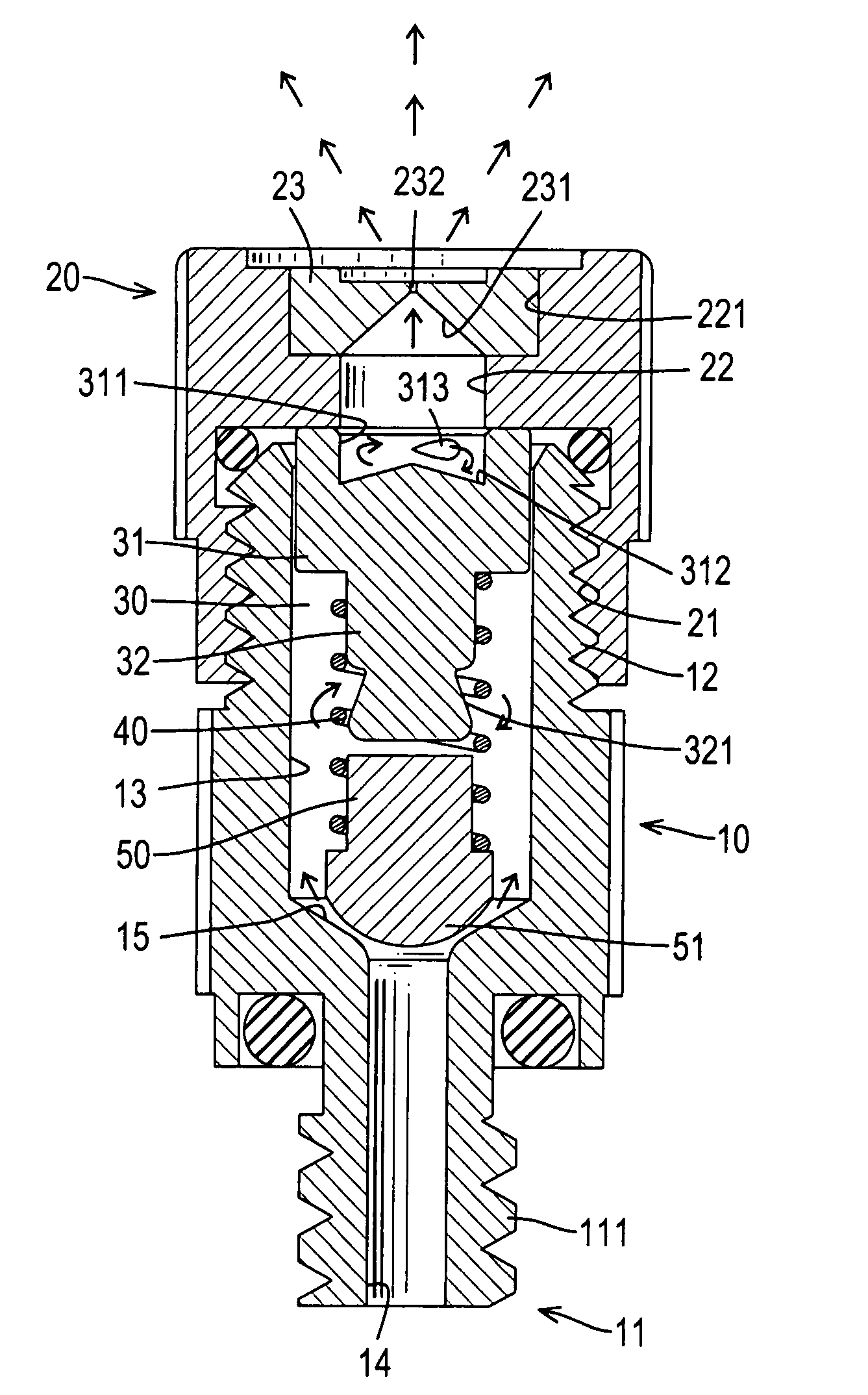
[0013]The main objective of the invention is to provide a spraying head assembly that reduces particles of liquid nebulization and raises a liquid ejection distance. The spraying head assembly has a tubular body, a cap, an upper plug, a lower plug and a spring. The tubular body has a connecting end, a spraying end, a connecting tube, a connecting channel and a chamber. The connecting tube is formed on and protrudes from the connecting end. The connecting channel is defined through the connecting tube and has a diameter. The chamber is defined in the spraying end, communicates with the connecting channel and has an inner surface and a diameter larger than that of the channel to define a shoulder between the chamber and the connecting channel. The cap is attached to the spraying end of the body and has a spraying end, a connecting end, a spraying channel, a conical cavity and a spraying hole. The connecting end is connected with the spraying end of the body. The spraying channel is defined in the cap. The conical cavity is defined inside the cap and communicates with the spraying channel. The spraying hole is defined in the spraying end of the cap and communicates with the conical cavity. The upper plug is held in the chamber in the body and comprises a spraying end, a connecting end, a head and a shaft. The head is smaller than the chamber so defines a gap between the head and the inner surface of the chamber and is formed on the spraying end of the upper plug and has a top abutting the cap, a bottom, a recess and multiple passages. The recess is defined in the top of the head, communicates with the spraying channel in the cap and has a conical bottom. The passages are defined in the head and communicate with the recess and the gap between the head and the inner surface of the chamber. The shaft is formed on and protrudes from the bottom of the head. The lower plug is mounted movably in the chamber in the body, is connected to the upper plug and has a top, a bottom, a post and a sealing block. The post is formed on the top of the lower plug. The sealing block is formed on the bottom of the lower plug to selectively close the connecting channel in the body. The spring is connected between the upper plug and the lower plug and has an upper end mounted around the shaft on the upper plug and a lower end mounted around the post on the lower plug. In this arrangement, a liquid supplied to the connecting end forms vortexes in the body to reduce particles of liquid nebulization and raise ejection speed and therefore distance.

Problems solved by technology

However, only one vortex occurs before the liquid is ejected from the conventional spraying head, so particles of the jet are large and only travel a short distance.
Therefore, a spraying range of the conventional spraying head is limited.

Method used


Image

  • Spraying head assembly
  • Spraying head assembly
  • Spraying head assembly

Examples


Embodiment Construction

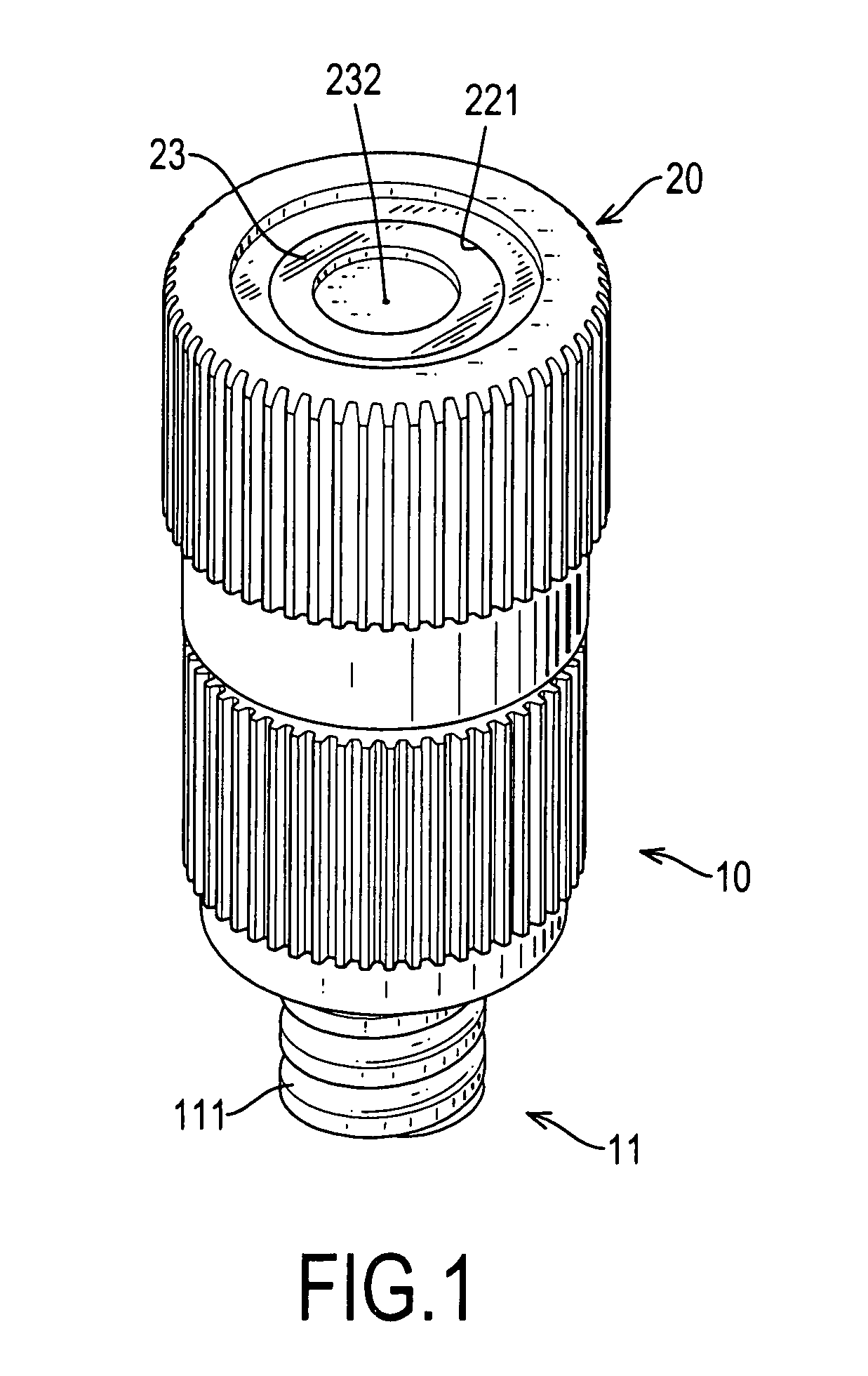
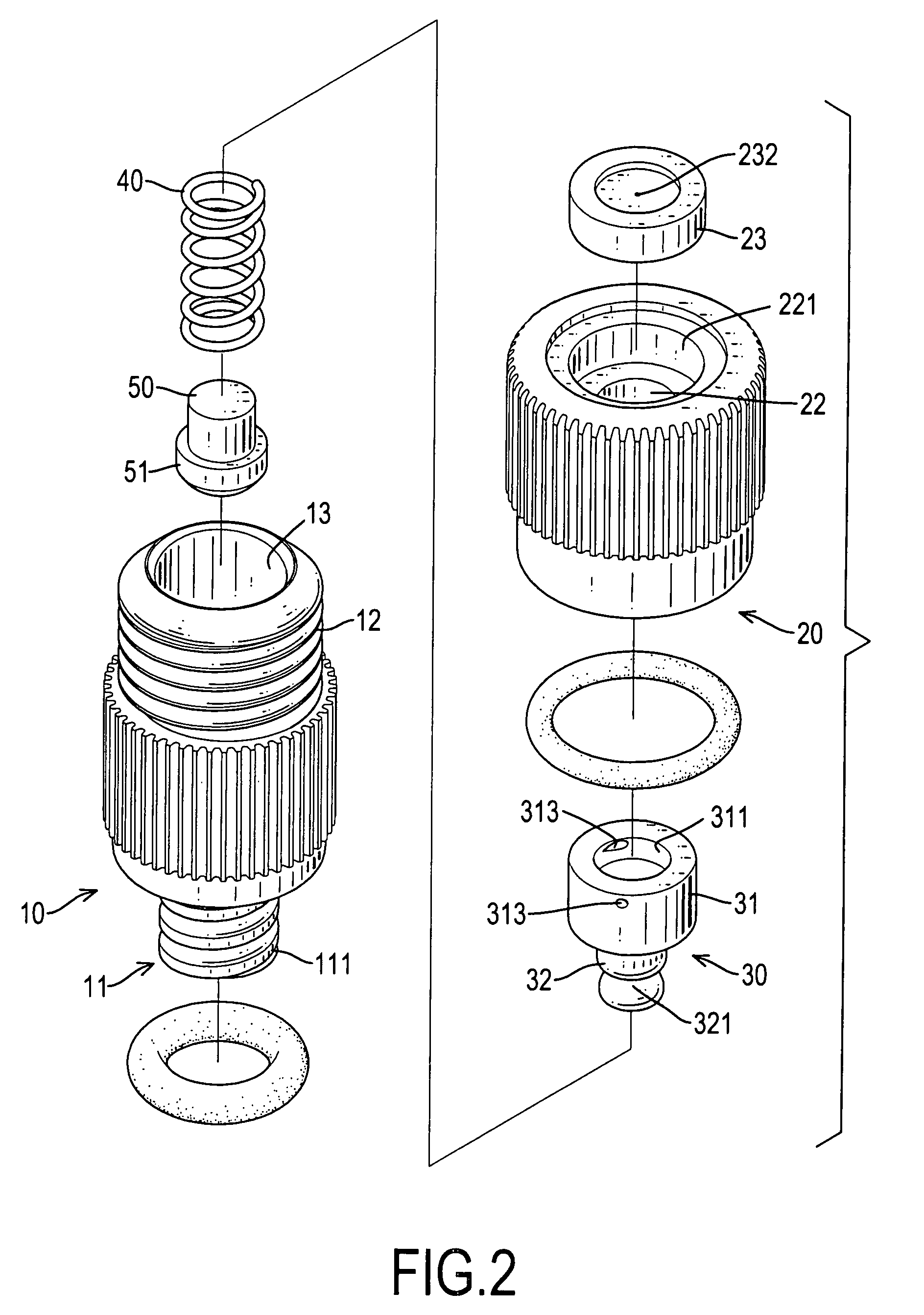
[0022]With reference to FIGS. 1 to 3, a spraying head assembly in accordance with the present invention comprises a body (10), a cap (20), an upper plug (30), a lower plug (50) and a spring (40). The body (10) is tubular and has a connecting end, a spraying end, a connecting tube (11), a connecting channel (14), a chamber (13) and two outer threads (111,12). The connecting tube (11) is formed on and protrudes from the connecting end. The connecting channel (14) is defined through the connecting tube (11) and has a diameter. The chamber (13) is defined in the spraying end, communicates with the connecting channel (11) and has an inner surface and a diameter larger than that of the channel (11) to define a shoulder (15) between the chamber (13) and the connecting channel (14). The shoulder (15) between the chamber (13) and the connecting channel (14) may be conical and formed concavely from the body. The outer threads (111,12) are formed respectively on the connecting end and the spra...


PUM


Abstract

A spraying head assembly has a tubular body, a cap, an upper plug, a lower plug and a spring. The cap is attached to the body and has a spraying channel, a conical cavity and a spraying hole. The conical cavity is defined inside the cap and communicates with the spraying channel and the spraying hole. The upper plug is held in the body and comprises a spraying end, a connecting end, a head and shaft. The head has a recess communicating with the spraying channel having a conical bottom. Multiple passages are defined in the head and communicate with the recess. The lower plug is mounted movably in the chamber in the body and is connected to the upper plug using the spring. In this arrangement, a liquid supplied to the connecting end forms vortexes in the body to reduce particles of liquid nebulization and raise ejection speed and therefore distance.

Description

BACKGROUND OF THE INVENTION[0001]1. Field of the Invention[0002]The present invention relates to a spraying head assembly, and more particularly to a spraying head assembly that reduces liquid nebulization and raises a liquid ejection distance.[0003]2. Description of Related Art[0004]With reference to FIGS. 6 and 7, a conventional spraying head is used to spray liquids and comprises a body (60), a cap (61), a pressing tab (611), an upper plug (62), a lower plug (64) and a spring (63). The body (60) is tubular and has a spraying end, a connecting end, a chamber (601) and a connecting channel (602). The connecting end of the body (60) is connected to a pipe using threads. The chamber (601) and the connecting channel (602) are defined respectively in the spraying end and connecting ends of the body (60) and communicate with each other to define a shoulder between the chamber (601) and the connecting channel (602).[0005]The cap (61) is attached to the spraying end and has a through hole...

Claims


Application Information

Patent Timeline
Patent Type & Authority Patents(United States)
IPC IPC(8): B05B1/30
CPCB05B1/3013B05B1/3426B05B1/3436B05B1/3473
Inventor CHANG, MING-SHEH
Owner TANONG PRECISION TECH CO LTD
Why Eureka
Eureka Blog
Learn More