
Fixing means for heat dissipater

a technology of heat dissipation means and heat dissipation chambers, which is applied in the direction of lighting and heating apparatus, semiconductor/solid-state device details, furniture parts, etc., can solve the problems of substantial reduction of heat dissipation efficiency, and achieve the effect of accurately pressing the gravity center and efficiently pressing the gravity center

Active Publication Date: 2008-12-02
CHEMTRON RES
View PDF16 Cites 29 Cited by
  • Summary
  • Abstract
  • Description
  • Claims
  • Application Information

AI Technical Summary

Benefits of technology

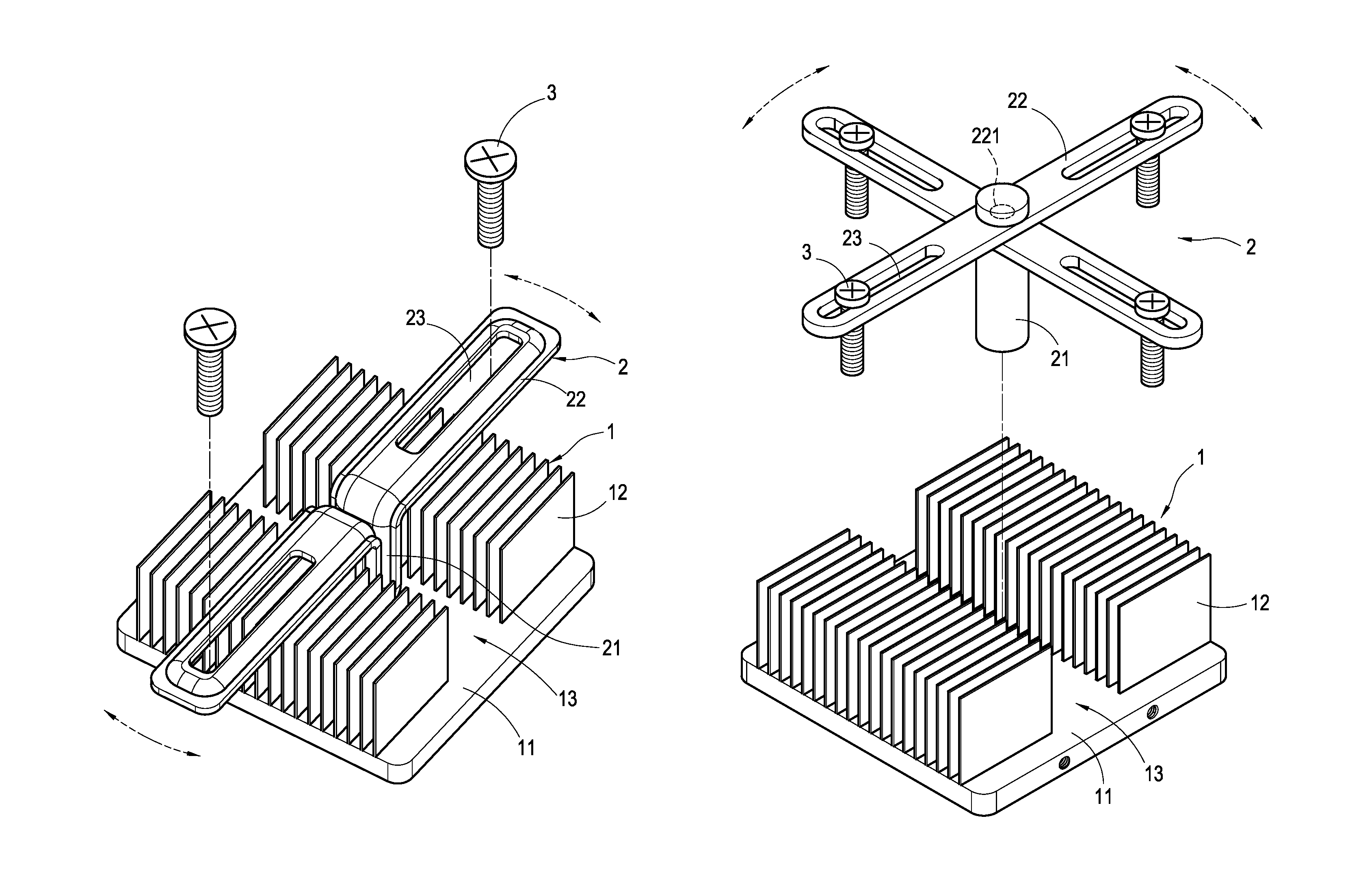
"The present invention provides a fixing means for a heat dissipater that has a positioning and pressing effect. The heat-dissipating base has a sliding groove with a positioning frame that can accurately press the gravity center of the heat dissipater via the positioning of the pressing end. This ensures a tight connection between the heat dissipater and the heat-generating element. The positioning frame is formed into a T-lettered shape and constituted of a transverse rod and a pressing end. The pressing end is accommodated in the sliding groove of the base to abut against the surface of the base. Both side faces of the transverse rod are provided with a screw hole, respectively, for receiving a locking element. The downward force generated by the connection of the locking element can cause the pressing end of the positioning frame to abut against the surface of the base, thereby efficiently fixing the position of the heat dissipater with respect to the heat-generating element."

Problems solved by technology

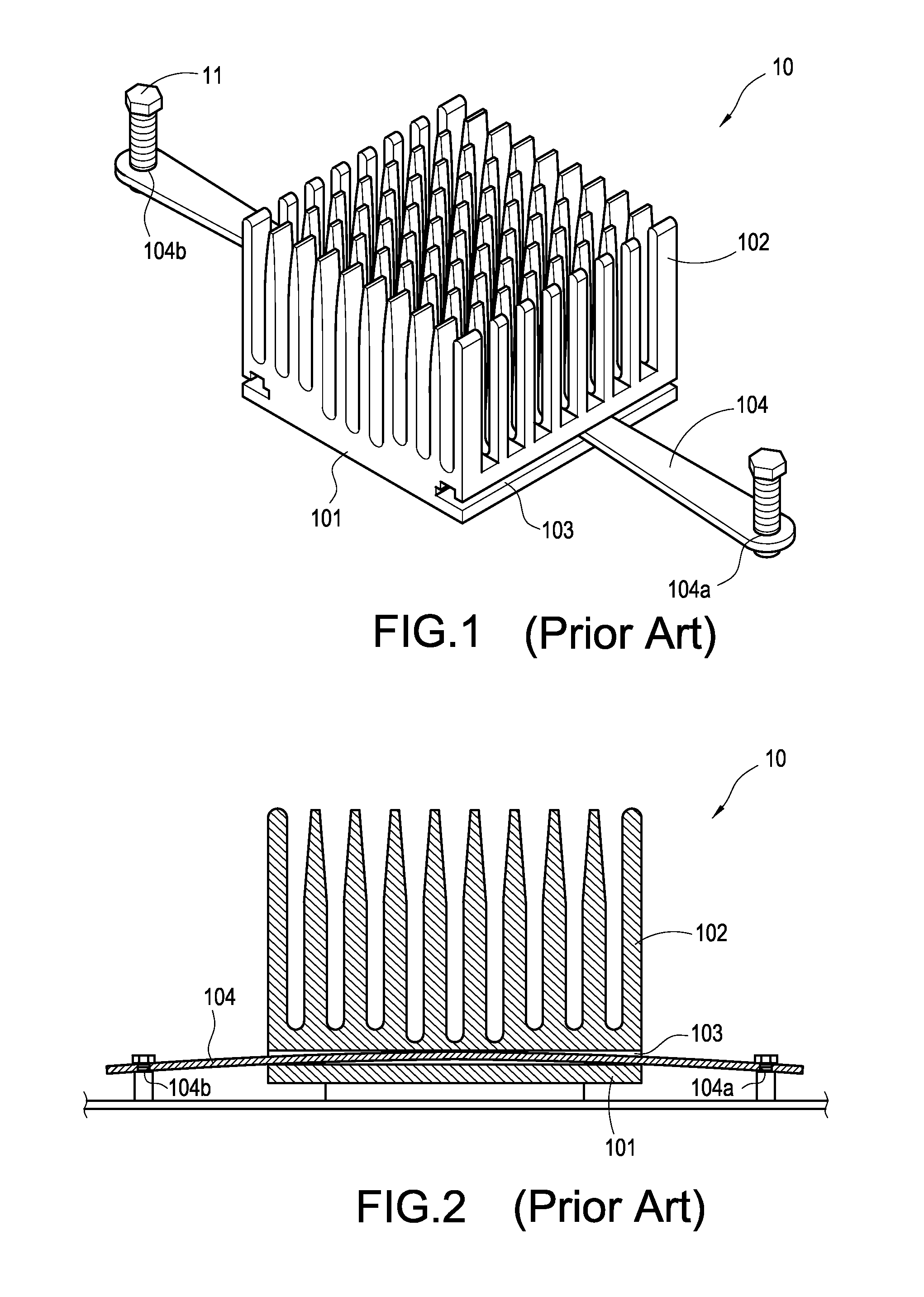
In view of this, it is an important issue to develop how to firmly connect the heat-generating element with the heat-dissipating structure having a plurality of heat-dissipating pieces.
However, since the electronic device having the heat-dissipating structure may be hit during the conveyance or other such situations, deviation or displacement may inevitably occur at the connecting surfaces, connected by adhesives, of the base of the heat-dissipating structure and the heat-generating element, which substantially reduces the heat-dissipating efficiency.

Method used


Image

  • Fixing means for heat dissipater
  • Fixing means for heat dissipater
  • Fixing means for heat dissipater

Examples


Embodiment Construction

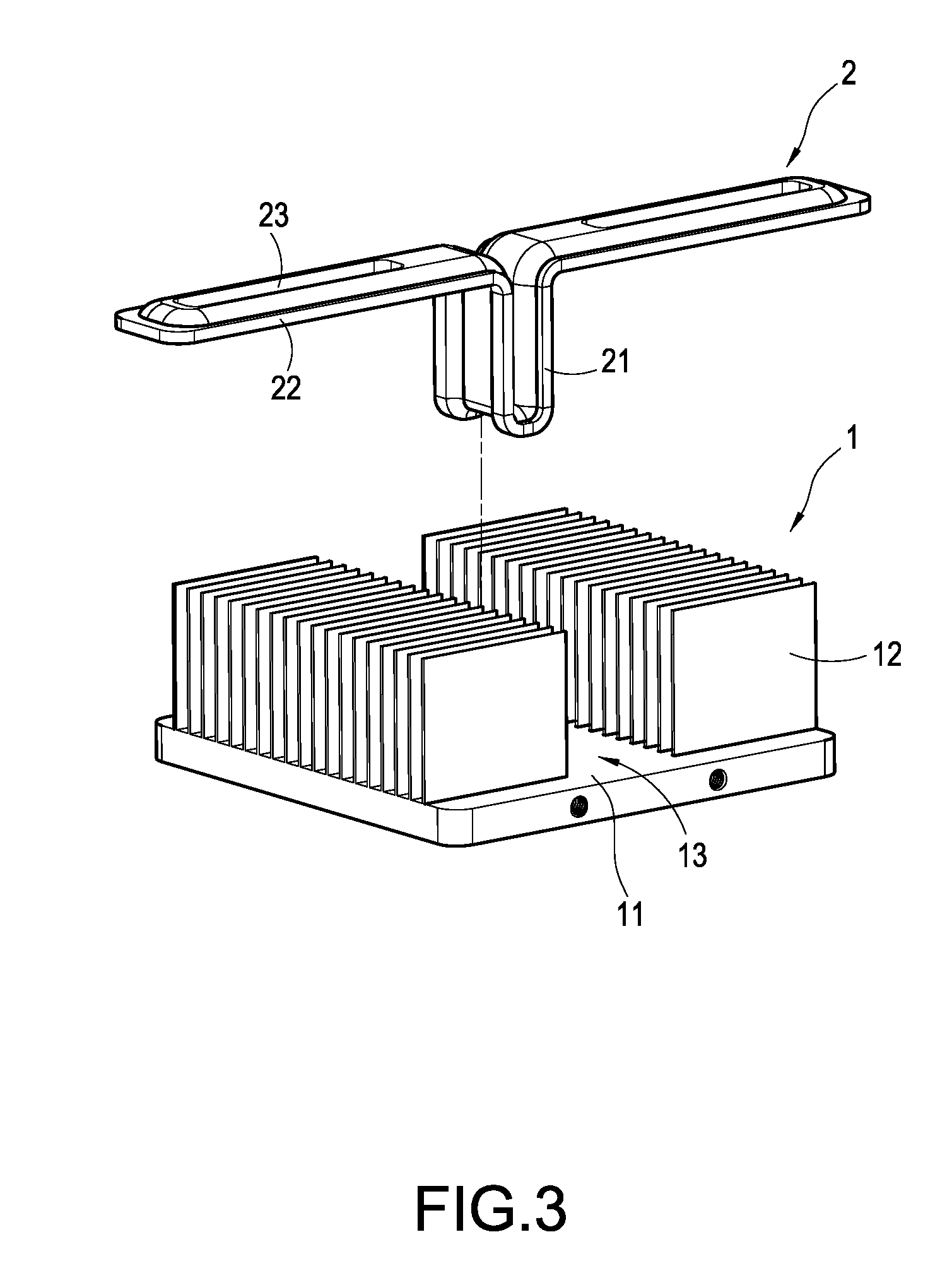
[0017]With reference to FIG. 3, it is an exploded view showing the structure of the present invention. The present invention comprises a heat-dissipating base 1 and a positioning frame 2. One surface of the base 1 is provided with a plurality of parallel heat-dissipating pieces 12. The center of the plurality of heat-dissipating pieces 12 is provided with a sliding groove 13 perpendicular to the orientation of the heat-dissipating pieces 12. Further, the positioning frame 2 is formed into a T-lettered shape and constituted of a pressing end 21 and a transverse rod 22. The pressing end 21 is located at a central position of the transverse rod 22 and accommodated in the sliding groove 13 of the base 1 to abut against the surface 11 of the base 1. In the present embodiment, the pressing end 21 is bent to form into a pillar-like shape. The pressing end 21 and the transverse rod 22 are integrally formed into a T-lettered shape. The transverse rod 22 of the positioning frame 2 is flat. Bo...


PUM


Abstract

A fixing means for a heat dissipater is provided to position the heat dissipater and a heat-generating element, which includes a heat-dissipating base and a positioning frame. The surface of the heat-dissipating base is provided with a plurality of heat-dissipating pieces. The center of the plurality of heat-dissipating pieces is provided with a sliding groove. Further, the positioning frame is formed into a T-lettered shape and constituted of a transverse rod and a pressing end. The pressing end is accommodated in the sliding groove of the base to abut against the surface of the base. Both side faces of the transverse rod are provided with a screw hole, respectively, for receiving a locking element. With the downward force generated by the connection of the locking element, the pressing end of the positioning frame can be caused to abut against the surface of the base, thereby to efficiently press the gravity center of the base and fix the position of the heat dissipater with respect to the heat-generating element.

Description

BACKGROUND OF THE INVENTION[0001]1. Field of the Invention[0002]The present invention relates to a heat-dissipating structure, and in particular to means for fixing a heat dissipater.[0003]2. Description of Prior Art[0004]With the increasing demand for a compact size, electronic devices are continuously developed to be more and more compact, causing a demand for a high heat-dissipating efficiency. Therefore, in order to enhance the heat-dissipating efficiency of the electronic device, a most common way of dissipating heat is to directly assemble a heat-dissipating assembly onto a heat-generating element. Especially, a heat-dissipating structure with a plurality of heat-dissipating pieces having high heat-dissipating efficiency is brought into direct contact with the heat-generating element via a heat-conducting medium, thereby to enhance the heat-dissipating performance of the heat-generating element. In view of this, it is an important issue to develop how to firmly connect the hea...

Claims


Application Information

Patent Timeline
Patent Type & Authority Patents(United States)
IPC IPC(8): H05K7/20A47B97/00
CPCH01L23/4006H01L2023/405H01L2023/4062H01L2023/4081H01L2924/0002H01L2924/00
Inventor LIAO, CHIH-PENGHUANG, YI-HE
Owner CHEMTRON RES
Learn More