
Method and apparatus for detecting a load change upon a structure and analyzing characteristics of resulting damage

a technology of load change and structure, applied in the field of structural health monitoring, can solve the problems of complex structure, inability to detect the presence of such load change, etc., to achieve the effect of facilitating the determination of the location

Active Publication Date: 2008-12-02
ACELLENT TECH
View PDF48 Cites 29 Cited by
  • Summary
  • Abstract
  • Description
  • Claims
  • Application Information

AI Technical Summary

Benefits of technology

"The invention is a system for monitoring the health of structures using passive sensors and actuators. The system receives a load change that generates a damage region on the structure, and the actuators transmit stress waves through the structure to determine the location and size of the damage region. The system can also include switches that establish electrical connections with both the sensors and actuators. The technical effect of the invention is to provide a reliable and efficient method for identifying and locating damage to structures, allowing for timely maintenance and repair."

Problems solved by technology

While many advances have been made, the field continues to be challenged by an increased need to develop “smart” systems.
However, these systems often do little more than detect the presence of such load changes, with any diagnosis or further analysis being left to other systems.
In contrast, purely active systems exist that are capable of querying a structure to determine its dynamic characteristics, but these active systems also suffer from their own drawbacks.
For instance, active systems must constantly query the structure, resulting in wasted energy and expense when they are not needed.
Furthermore, because each of these systems often requires large numbers of sensors in order to be effective, structures often must have a variety of sensing elements placed at various locations.
Because individual sensing elements must often be placed separately, affixing a large array of such sensing elements can be tedious and time consuming.
In addition, as each individual sensing element can require one or, commonly, multiple wires, large arrays of sensing elements can require a large number of individual wires, which may be difficult to handle and keep track of.
The securing of such large numbers of wires can often be painstaking and time consuming, as well.

Method used


Image

  • Method and apparatus for detecting a load change upon a structure and analyzing characteristics of resulting damage
  • Method and apparatus for detecting a load change upon a structure and analyzing characteristics of resulting damage
  • Method and apparatus for detecting a load change upon a structure and analyzing characteristics of resulting damage

Examples


Embodiment Construction

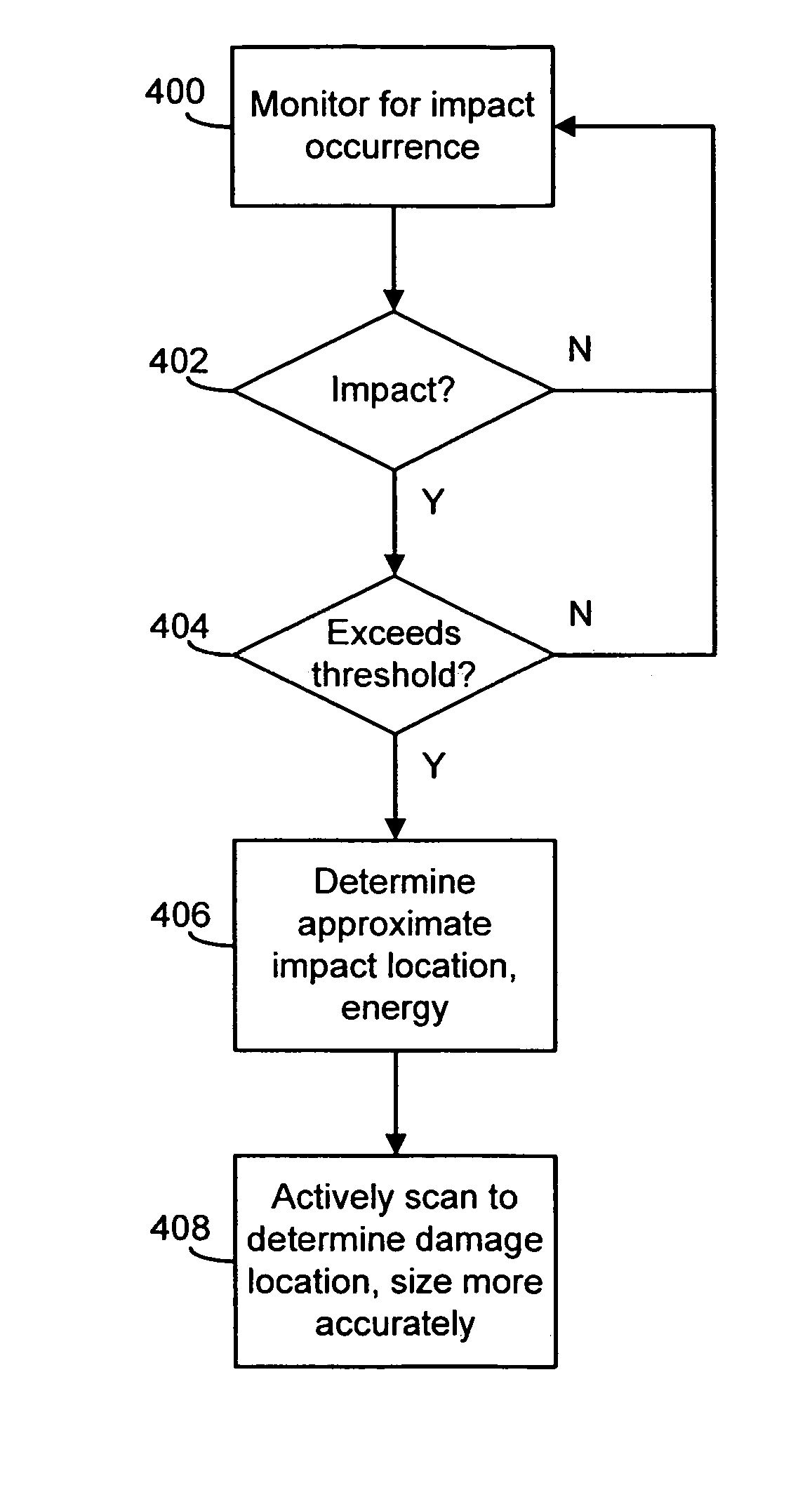
[0034]In one embodiment of the invention, a sensor network is attached to a structure and employed to detect and analyze load changes. The sensor network has transducers, capable of acting as both passive sensors and active actuators, integrated within it. In a passive mode, the transducers detect load changes upon the structure, such as impacts. Upon detection of a load change, the transducers are engaged in an active mode to actively scan the impact area to determine the location and size of any resulting damage region. In this manner, passive and active systems are integrated within a single, convenient layer that possesses the best features of both active systems and passive systems.

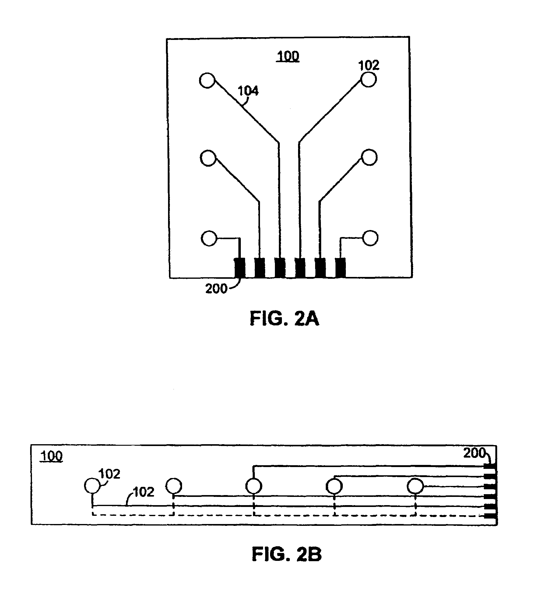
[0035]For ease of installation, the sensor network can be placed on a flexible dielectric substrate to form a diagnostic layer. FIG. 1A illustrates such a flexible diagnostic layer for use in accordance with embodiments of the present invention. A diagnostic layer 100 is shown, which contains an arra...


PUM

PropertyMeasurementUnit
sizeaaaaaaaaaa
surface areaaaaaaaaaaa
stressaaaaaaaaaa

Abstract

A sensor network is attached to a structure and employed to detect and analyze load changes. The sensor network has transducers, capable of acting as both passive sensors and active actuators, integrated within it. In a passive mode, the transducers detect load changes upon the structure, such as impacts. Upon detection of a load change, the transducers are engaged in an active mode to actively scan the impact area to determine the location and size of any resulting damage region. In this manner, passive and active systems are integrated within a single, convenient layer that possesses the best features of both active systems and passive systems.

Description

BACKGROUND OF THE INVENTION[0001]This application claims the benefit of U.S. Provisional Patent Application No. 60 / 613,825, filed on Sep. 27, 2004, which is incorporated herein by reference in its entirety.BRIEF DESCRIPTION OF THE INVENTION[0002]The present invention relates generally to structural health monitoring. More specifically, the present invention relates to the detection of load changes upon a structure, and the analysis of characteristics of any resulting damage.BACKGROUND OF THE INVENTION[0003]The diagnostics and monitoring of structures, such as that carried out in the structural health monitoring field, are often accomplished by employing arrays of sensing elements. While many advances have been made, the field continues to be challenged by an increased need to develop “smart” systems. For example, purely passive systems exist for detecting impacts and other load changes. However, these systems often do little more than detect the presence of such load changes, with a...

Claims


Application Information

Patent Timeline
Patent Type & Authority Patents(United States)
IPC IPC(8): G01N29/04G01B17/00
CPCG01N29/043G01N29/045G01N29/07G01N29/11G01N29/2475G01N29/262G01N2291/0231G01N2291/0258G01N2291/0427G01N2291/106
Inventor BEARD, SHAWN J.QING, XINLINCHAN, HIAN LENGZHANG, CHANGCHANG, FUO-KUO
Owner ACELLENT TECH
Learn More