
Image-based rendering and editing method and apparatus

a three-dimensional model and image-based technology, applied in the field of image-based rendering and editing methods and apparatuses, can solve the problems of complex algorithms, inability to meet the requirements of conventional mesh-based generating techniques using polygonal meshes, and inability to transmit compressed meshes. to achieve the effect of improving rendering speed and quality

Inactive Publication Date: 2008-11-18
SAMSUNG ELECTRONICS CO LTD
View PDF1 Cites 17 Cited by
  • Summary
  • Abstract
  • Description
  • Claims
  • Application Information

AI Technical Summary

Benefits of technology

[0009]According to an aspect of the present invention, there is provided a method and apparatus for removing redundant data of a simple texture model that render the same portion of a 3D model from different viewpoints, which can improve rendering speed and quality.
[0010]According to another aspect of the present invention, there is provided a rendering method and apparatus, which can successfully render surface characteristics of a 3D model, such as glitter and shade, which vary from viewpoint to viewpoint.

Problems solved by technology

However, a conventional mesh-based generating technique using a polygonal mesh has failed to meet this requirement satisfactorily.
In order to simplify such complex meshes, however, complex algorithms are necessary.
In addition, complex algorithms are also needed to compress meshes and transmit the compressed meshes progressively.
The conventional image-based rendering technique, however, renders the 3D model without considering the fact that reference images of the 3D model may include redundant data of the simple texture model that render the same portion of the 3D model from different viewpoints, thereby considerably degrading the rendering speed and quality.
In addition, the conventional image-based rendering technique cannot satisfactorily render various surface characteristics of a 3D model, such as glitter or shade varying from viewpoint to viewpoint.
Therefore, a 3D model rendered by the conventional image-based rendering technique may not be realistic.
Moreover, the conventional mesh-based rendering technique needs complex algorithms because it provides no other option but to modify every reference image of an image-based 3D model in order to modify the image-based 3D model, in which case, the amount of image data needed to be edited is considerable.

Method used


Image

  • Image-based rendering and editing method and apparatus
  • Image-based rendering and editing method and apparatus
  • Image-based rendering and editing method and apparatus

Examples


Embodiment Construction

[0057]Reference will now be made in detail to the embodiments of the present invention, examples of which are illustrated in the accompanying drawings, wherein like reference numerals refer to the like elements throughout. The embodiments are described below to explain the present invention by referring to the figures.

[0058]In the present invention, a three-dimensional (3D) model is generated using a simple texture model. The simple texture model includes reference images, which render different aspects of the 3D model. Each of the reference images contains geometrical information (i.e., depth information), information on a camera, such as the location, direction, and field-of-view of the camera, and information on near and far clipping planes.

[0059]FIG. 1 illustrates one example of the simple texture model. More specifically, color images of a simple texture model are illustrated in the upper half of FIG. 1, depth images of the simple texture model are illustrated in the lower half...

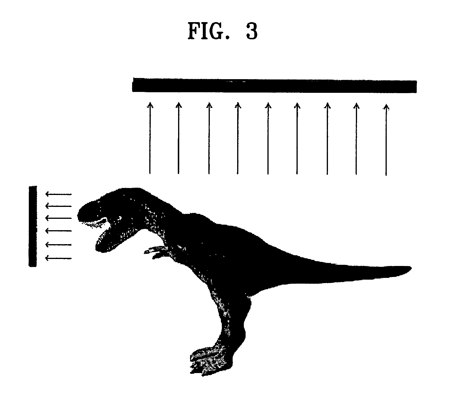

PUM


Abstract

A method and apparatus removing redundant data of a simple texture model, using an extended depth image, and an image-based editing method and apparatus. The method involves calculating normal vectors of pixels projected into a three-dimensional (3D) space by using depth images among a plurality of simple texture images, the plurality of simple texture images rendering different aspects of a 3D model; calculating reliabilities of the pixels of each of the simple texture images by using the calculated normal vectors; and comparing the reliabilities of the pixels that originate from different simple texture images but render the same portion of the 3D model and removing the pixels having low reliabilities from the different simple texture images from which they respectively originate.

Description

CROSS-REFERENCE TO RELATED APPLICATION[0001]This application claims the priority of Korean Patent Application No. 2003-48110, filed on Jul. 14, 2003, in the Korean Intellectual Property Office, the disclosure of which is incorporated herein by reference.BACKGROUND OF THE INVENTION[0002]1. Field of the Invention[0003]The present invention relates to methods and apparatuses for generating and editing a three-dimensional (3D) model, and more particularly, to methods and apparatuses for generating and editing a 3D model, which can more precisely generate a 3D model and can more quickly edit the 3D model using depth information of the 3D model.[0004]2. Description of the Related Art[0005]Since the first research into 3D graphics, one of the most fundamental goals of 3D graphics has always been to generate 3D models more precisely and more quickly. Recent multimedia applications require user devices, such as mobile devices, to more quickly and more precisely generate 3D models in a networ...

Claims


Application Information

Patent Timeline
Patent Type & Authority Patents(United States)
IPC IPC(8): G06T15/00G06T15/80
CPCG06T15/205G11B27/034H04N19/597G06T17/00G06T15/10
Inventor PARK, IN-KYUHAN, JOO-YEONHAN, MAHN-JINIGNATENKO, ALEXEY VICTOROVICHKONOUCHINE, ANTONLEVKOVICH-MASLYUK, LEONID IVANOVICH
Owner SAMSUNG ELECTRONICS CO LTD
Learn More