Hydrocarbon-reforming catalyst and a method of manufacturing thereof
a technology of hydrocarbons and catalysts, which is applied in the field of hydrocarbon-reforming catalysts, can solve the problems of wasteful consumption of expensive catalytic-activity constituents, unavoidable introduction of excess steam, and heavy carbonaceous matter deposition, and achieves excellent activity, prevent accumulation, and high dispersion
Inactive Publication Date: 2008-11-18
JAPAN PETROLEUM EXPLORATION CO LTD
View PDF33 Cites 15 Cited by
- Summary
- Abstract
- Description
- Claims
- Application Information
AI Technical Summary
Benefits of technology
[0014]Accumulation of carbonaceous matters is suppressed by minimizing a catalytic-activity constituent, which is supported on a carrier, to fine particles. An effect of particle size of the catalytic-activity constituent on accumulation of carbonaceous matters probably explained by acceleration of reverse reactions compared with the carbonaceous matter-depositing reactions (5) to (8) in correspondence to minimization of the catalytic-activity particles. An oxidizing power of the catalytic-activity particles present on a surface of the carrier for reactions of C+O2→CO2 and C+CO2→2CO may be also effective for prevention of the accumulation. As particle size of the catalytic-activity constituent is smaller, the carbonaceous ma
Problems solved by technology
Heavy deposition of the carbonaceous matters produces unfavorable results.
Deposition of the carbonaceous matters on the surface of the catalyst is avoided by introducing an excess volume of steam, but introduction of excess steam unavoidably increases an energy cost and needs a large-scaled plant.
In this sense, an expensive catalytic-act
Method used
View moreImage
Smart ImageViewing Examples
Examples
 PUM
| Property | Measurement | Unit |
|---|---|---|
| Fraction | aaaaa | aaaaa |
| Nanoscale particle size | aaaaa | aaaaa |
| Catalyst | aaaaa | aaaaa |
Abstract
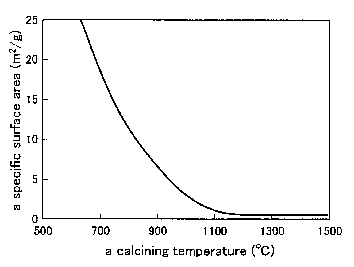
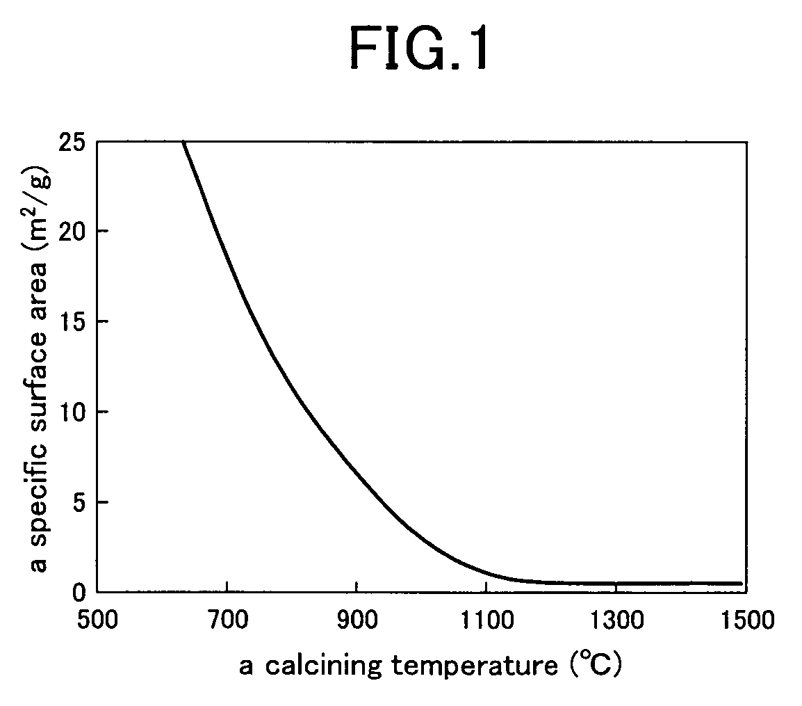
A porous preform (carrier) is soaked in an impregnating solution, which contains both of a catalytic-activity constituent, e.g. Ni and/or Co, and a carrier-forming constituent, e.g. Mg, Al, Zr, Ti and/or Ca, so as to simultaneously infiltrate the catalytic-activity and carrier-forming constituents into the porous preform. The impregnated preform is dried, calcined at a temperature of 700° C. or higher and then activated at a temperature of 500° C. or higher, whereby fine catalytic-activity particles are distributed on a surface of the porous carrier with high dispersion. Due to finely-distributed catalytic-activity particles, the surface of the catalyst is prevented from deposition of carbonaceous matters during reformation of hydrocarbon and held in an active state over a long term.
Description
INDUSTRIAL FIELD[0001]The present invention relates to a catalyst for hydrocarbon-reforming that is employed when producing carbon monoxide and hydrogen from hydrocarbon such as methane, and also relates to a method of manufacturing the catalyst.BACKGROUND[0002]When a hydrocarbon, e.g. methane, natural gas, petroleum gas, naphtha, heavy oil or crude oil, is reacted with a reforming agent, e.g. steam, air or carbon dioxide, at a high temperature in presence of a catalyst, the hydrocarbon is reformed to a synthetic gas that is a mixed gas containing carbon monoxide and hydrogen. The synthetic gas is useful as a raw material of methanol, liquid fuel, etc. Research and development have been also carried out in order to separate hydrogen from the synthetic gas in response to advancement of fuel cells in these days. Nickel / alumina and nickel / magnesia / alumina have been used so far as hydrocarbon-reforming catalysts for production of such a synthetic gas.[0003]In a hydrocarbon / steam reactin...
Claims
Login to View More Application Information
Patent Timeline
 IPC IPC(8): B01J23/00B01J20/00B01J21/00C01B3/40B01J23/75B01J23/755B01J23/78B01J35/10B01J37/02B01J37/14B01J37/18C01B32/40
CPCB01J23/75B01J23/755B01J23/78C01B3/40B01J35/006B01J35/0066B01J35/1009B01J35/1014B01J37/0201C01B2203/0233C01B2203/0238C01B2203/1052C01B2203/1241C01B2203/1247Y02P20/52Y02P20/141
Inventor WAKATSUKI, TOSHIYAINABA, KIYOSHINAKAJIMA, HIDEYUKIHOSOYA, EIICHI
Owner JAPAN PETROLEUM EXPLORATION CO LTD
Features
- R&D
- Intellectual Property
- Life Sciences
- Materials
- Tech Scout
- Unparalleled Data Quality
- Higher Quality Content
- 60% Fewer Hallucinations
Learn More Browse by: Latest US Patents, China's latest patents, Technical Efficacy Thesaurus, Application Domain, Technology Topic, Popular Technical Reports.
© 2025 PatSnap. All rights reserved.Legal|Privacy policy|Modern Slavery Act Transparency Statement|Sitemap|About US| Contact US: help@patsnap.com


