
Headlamp with a continuous long-distance illumination without glaring effects

a long-distance, headlamp technology, applied in vehicle lighting systems, lighting and heating apparatuses, light fastenings, etc., can solve the problems of reducing illumination intensity, failure to prevent, loss of part of the generated light, etc., to improve the view distance and vision quality, improve the effect of illumination and safety and comfort driving

Inactive Publication Date: 2008-11-18
ALCELIK TURHAN
View PDF70 Cites 37 Cited by
  • Summary
  • Abstract
  • Description
  • Claims
  • Application Information

AI Technical Summary

Benefits of technology

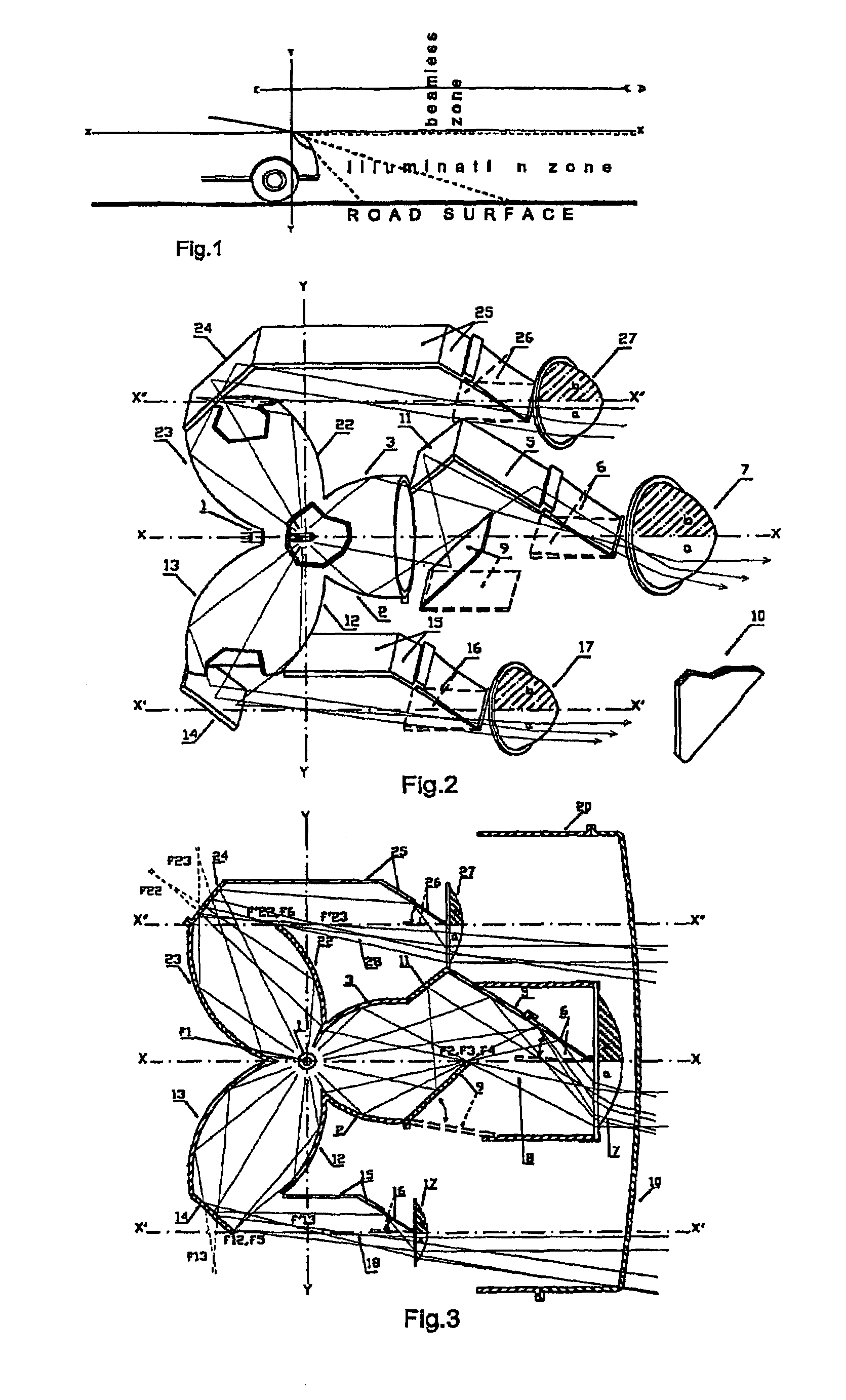
[0022]In order to resolve said conventional problems, the present invention provides a headlamp design wherein the light source and all the direct and indirect reflecting surfaces are totally concealed from the opposite traffic, and the light generated by a light source is reflected and focused by specially designed reflectors or reflecting surfaces and then directed to a plano-convex lens, the upper half of which is closed with a semi-shutter and only the lower half is utilized to ensure that the light rays are horizontal to the travel direction and do not pass above the horizontal light plane, providing an half-lens illumination with the exact adjustment of the height of the light plane.
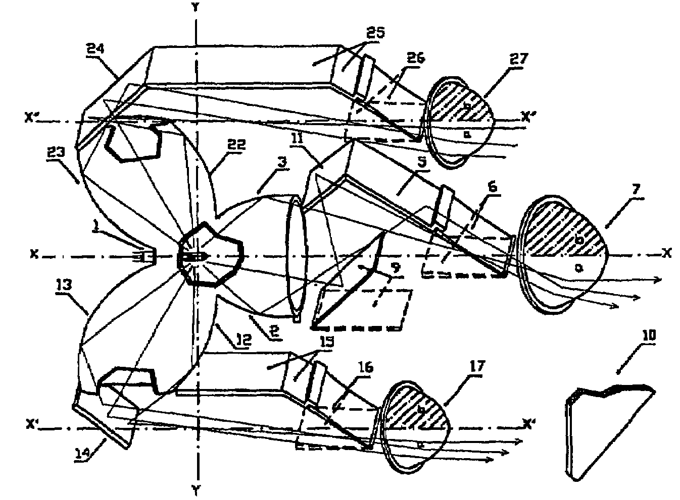
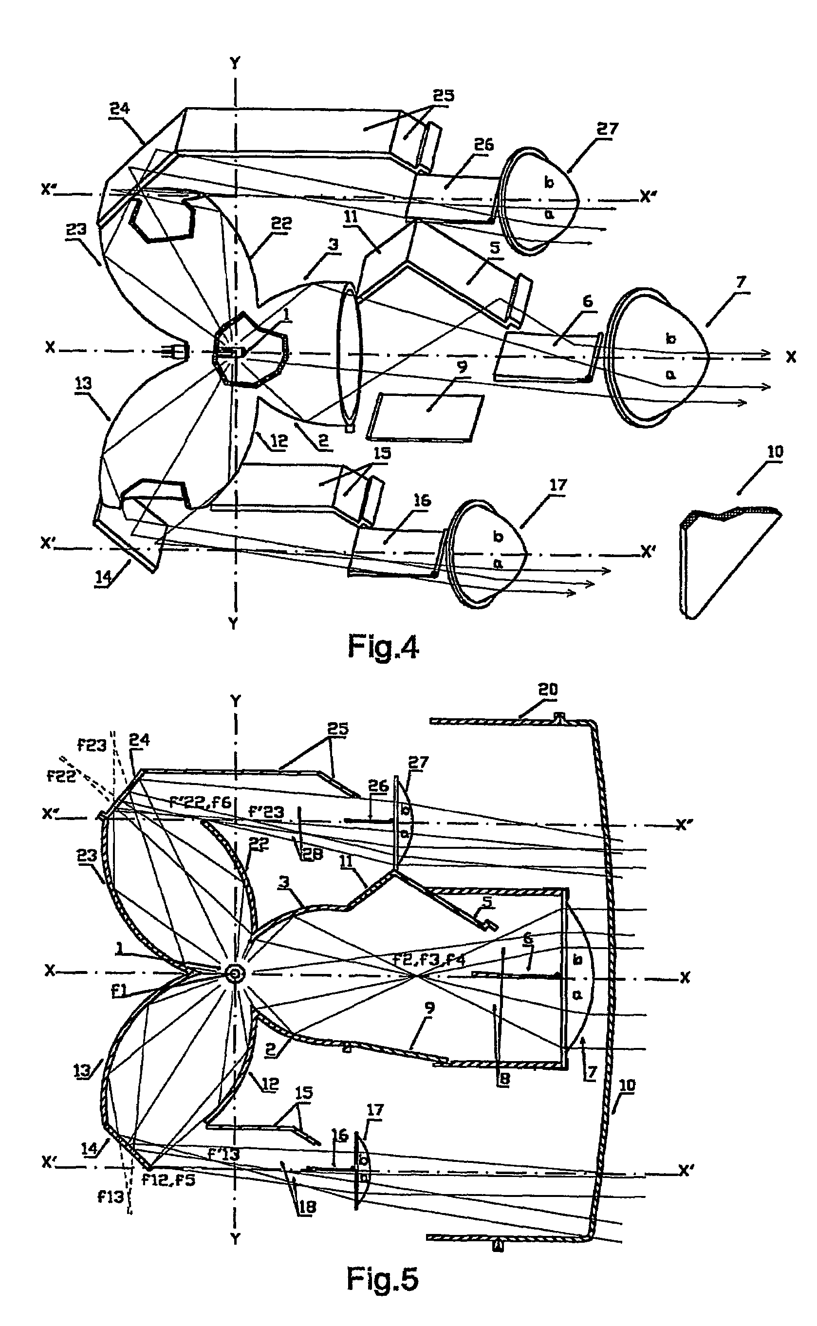
[0023]The most preferred embodiment of this invention consists of a single standard light source, a reflector group of three units forming a triple light pathway structure similar to a clover-leaf, with each unit having its own light pathway comprised of reflector surfaces, a piano-convex lens and a movable semi-shutter covering the upper half of the said plano-convex lens, thereby allowing to utilize in the most efficient manner the light generated by the light source for illumination.
[0024]The headlamp in the present invention, thanks to the inner design, ensures a total concealment of the light source and all the direct and indirect reflecting surfaces, therefore causing no glaring effects on the oncoming traffic, while providing an even better illumination compared with conventional headlamp designs, since it allows the utilization of nearly all the light generated by the light source.
[0025]Another object of this invention is to obtain combined positive effects of vehicle approaching vehicle each other, and to improve the view distance and the vision quality for vehicles traveling in the same direction as well as for opposing vehicles.
[0026]A further object of this invention is to ensure a headlamp design that allows the rearview mirror to be used in “daytime view” mode during nighttime driving, thus providing a safer and more comfortable driving.

Problems solved by technology

While some of these arts provide sufficient illumination, they fail to prevent glaring effects, and others prevent glaring completely, but fail to ensure sufficient light intensity at appropriate distances or at least they cause the loss of part of the lights generated.
Since the light shield disposed in front of the reflector surface blocks part of the generated light rays in conventional projection type headlamp designs, illumination intensity is reduced and a full glare control may not be provided.
In some of the previous arts that are similar to our invention, the light source and the reflecting surfaces are not fully concealed from the opposite traffic, and thus glaring effects cannot completely be eliminated.
However, since it is not possible to obtain a parallel light beam in any of these methods, they fail to provide a sufficient illumination at desired distances.

Method used


Image

  • Headlamp with a continuous long-distance illumination without glaring effects
  • Headlamp with a continuous long-distance illumination without glaring effects
  • Headlamp with a continuous long-distance illumination without glaring effects

Examples


first embodiment

[0044]FIGS. 2, 3, 4 and 5 show the basic parts and the principle of operation of the headlamp in this invention, in the form of a clover-leaf, consisting of a single light source 1, a reflector group consisting of three reflector units, each of the said units looking forward 2,3, downward 12,13 and upward 22,23 respectively, and each reflector unit having its own light path assembly which will be described below in detail, a front lens 10 that is preferably a transparent lens and a headlamp housing 20 with fixing connections for the front lens.

[0045]The light source 1 used in this invention can be by any of standard light sources including incandescent, halogen, high intensity discharge (HID), light emitting diode (LED), fluorescent, and other types of lamps with sufficient light intensity approved internationally for motor vehicle applications without any limitations. Optical fiber based illuminations can also be used in the system as the light source. The light source 1 is so disp...

second embodiment

[0076]FIGS. 6, 7, 8 and 9 show the basic parts and the principle of operation of the headlamp in this present invention, in a form similar to clover-leaf, consisting of a single light source 1, a reflector group consisting of three reflector units, each unit looking forward 2,3, downward 12,13 and upward 22,23 respectively, each of the said reflector units having its own light pathway which will be described below in detail, a front lens 10 that is preferably a transparent lens and a headlamp housing 20 with fixing connections for the front lens.

[0077]The common light source 1 can be any type defined in the first embodiment, and it is so disposed that the filament or the discharge space of the said light source 1 is located near the common first focus f1 of each reflector unit.

[0078]The forward-looking part of the second embodiment (FIGS. 6, 7, 8 and 9) consists of reflector sections 2 and 3, a flat mirror 5, a semi-shutter 6, a piano-convex lens 7, and an opening 8 for light passag...


PUM


Abstract

A headlamp developed especially for motor vehicles based on the exact adjustment of the height of the light plane by total concealing the light source and all direct and indirect reflecting surfaces and by using the principle of the half-lens illumination described in this invention. The most preferred embodiment of this invention consists of a single standard light source (1), a reflector group of three units (2,3; 12,13; 22,23) forming a structure similar to a clover-leaf with each unit having its own light pathway, three plano-convex lenses (27,7,17), three flat mirrors (25,5,15), three movable semi-shutters (26,6,16) covering the upper halves of the plano-convex lenses, with the addition of a shield (9) and a reflective surface in the forward-looking part of this embodiment. The basic illumination principle defined above may be applied to headlamp designs with a single or multiple reflectors, or without a lens in the headlamp structure, and without any limitation in the number or direction of the reflectors.

Description

BACKGROUND OF THE INVENTION[0001]1. Field of the Invention[0002]This present invention relates generally to applications where it is desired to eliminate glaring effects of light on the eyes, and more specifically, to motor vehicle headlamps in order to obtain a continuous long-distance illumination without any glaring effects on the oncoming traffic and pedestrians during nighttime driving.[0003]2. Detailed Description of the Prior Art[0004]Numerous studies have been conducted on motor vehicle headlamps in order to provide a good illumination on the road surface in any type of weather and road conditions while ensuring the light beam does not cause any glaring on the eyes of the oncoming traffic users.[0005]Below is the summary of studies conducted in this field;[0006]Using a projection type headlamp (for example, U.S. Pat. No. 1,614,027 to R. Graf; U.S. Pat. No. 2,215,203 to Young; U.S. Pat. No. 6,007,223 to Futami; U.S. Pat. No. 6,220,736 to Dobler, et al.; and U.S. Pat. No. 6,41...

Claims


Application Information

Patent Timeline
Patent Type & Authority Patents(United States)
IPC IPC(8): F21V7/00F21S8/12F21Y101/00
CPCF21S48/1388F21S41/255F21S41/321F21S41/323F21S41/365F21S41/60F21S41/675F21S41/692
Inventor ALCELIK, TURHAN
Owner ALCELIK TURHAN
Learn More