Disk assembly having integral clamp and/or spacer

a technology of clamping and spacers, applied in the field of drive components, can solve the problems of loss of servo, data loss, deformation of top clamps and spacers, etc., and achieve the effect of ensuring assembly reliability much greater

Inactive Publication Date: 2008-11-04
HITACHI GLOBAL STORAGE TECH NETHERLANDS BV
View PDF18 Cites 0 Cited by
  • Summary
  • Abstract
  • Description
  • Claims
  • Application Information

AI Technical Summary

Benefits of technology

[0008]A composite disk-clamp assembly is claimed. The assembly includes a clamp or spacer of a resilient material coupled to the disk by injection molded plastic so that the clamp forms an integral portion of the disk itself. During manufacture, the clamp is positioned at the desired location in relation to the disk. Then the mold is closed to encompass the clamp and possibly a portion of the disk. Molten plastic is injected into the mold and allowed to cool sufficiently that the plastic will not become adversely deformed during subsequent processing steps. The resultant structure is a disk assembly with an integral clamp or spacer that will not radially slip during use in a drive, nor during a catastrophic event such as a drop or impact. Thus, the reliability of the assembly is much greater than was heretofore possible.
[0009]Because the disk and clamp and / or spacer are coupled together, a processing step during drive assembly is saved in that only one piece (clamp / spacer-disk composite) need be handled instead of many parts (clamp and spacers and disks). Additional cost savings are realized during manufacture of the clamp and spacers themselves, as it is longer necessary to machine surfaces to obtain a hardness match.
[0010]Also advantageously, the assembly can then be clamped to a spindle by a single coupling member (e.g., bolt or screw) extending through the central aperture of the assembly. Thus, multiple screw holes in the clamp and spacers are no longer required, and the resultant waviness is avoided. Also, because the disks are attached to the spindle using only the center hole, the size of the clamp and spacers can be reduced, thereby creating more usable disk surface.
[0011]Preferably, the disk and / or clamp and / or spacer have surface features that assist in keeping the molded plastic secure. For instance, a mechanical coupling to the plastic can be achieved by protrusions and corresponding receiving areas such as ridges / textured lines and coincident troughs. The mechanical coupling encourages the various components to expand and contract together, thereby maintaining the proper alignment. The disk and clamp or spacer can be formed or machined to have the desired surface features.
[0012]As an option, one or more reinforcing members can be added to the assembly to enhance the strength of the assembly. Also, various performance-enhancing additives may be added to injection molding compounds to accomplish various purposes. For instance, fillers can be added to increase bulk density, plasticizers can be added to improve processability and reduce product brittleness, antioxidants can be added to prevent polymer oxidation, stabilizers can be added to stabilize the polymer against heat or UV light, and reinforcing additives can be added to improve strength.
[0014]Additional cost savings would be realized during manufacture of the disk with integral clamp and / or spacer ring, as it would no longer be necessary to machine two surfaces in such a way to match flatness.

Problems solved by technology

Great pressure must be exerted by the bolts on the top clamp in order to prevent slippage of the disks in the event that the drive is bumped or uneven thermal expansion breaks the frictional coupling, because once the disks slip, the drive loses its servo and the data is lost.
A major drawback of the current practice is that when the bolts are tightened, the top clamp and spacer become deformed due to the uneven pressures exerted by the individual bolts.
Another issue encountered in the prior art is the high cost of assembling the drives.
This process is time consuming and requires either specialized equipment or manpower.

Method used


Image

  • Disk assembly having integral clamp and/or spacer
  • Disk assembly having integral clamp and/or spacer
  • Disk assembly having integral clamp and/or spacer

Examples


Embodiment Construction

[0035]The following description is the best embodiment presently contemplated for carrying out the present invention. This description is made for the purpose of illustrating the general principles of the present invention and is not meant to limit the inventive concepts claimed herein.

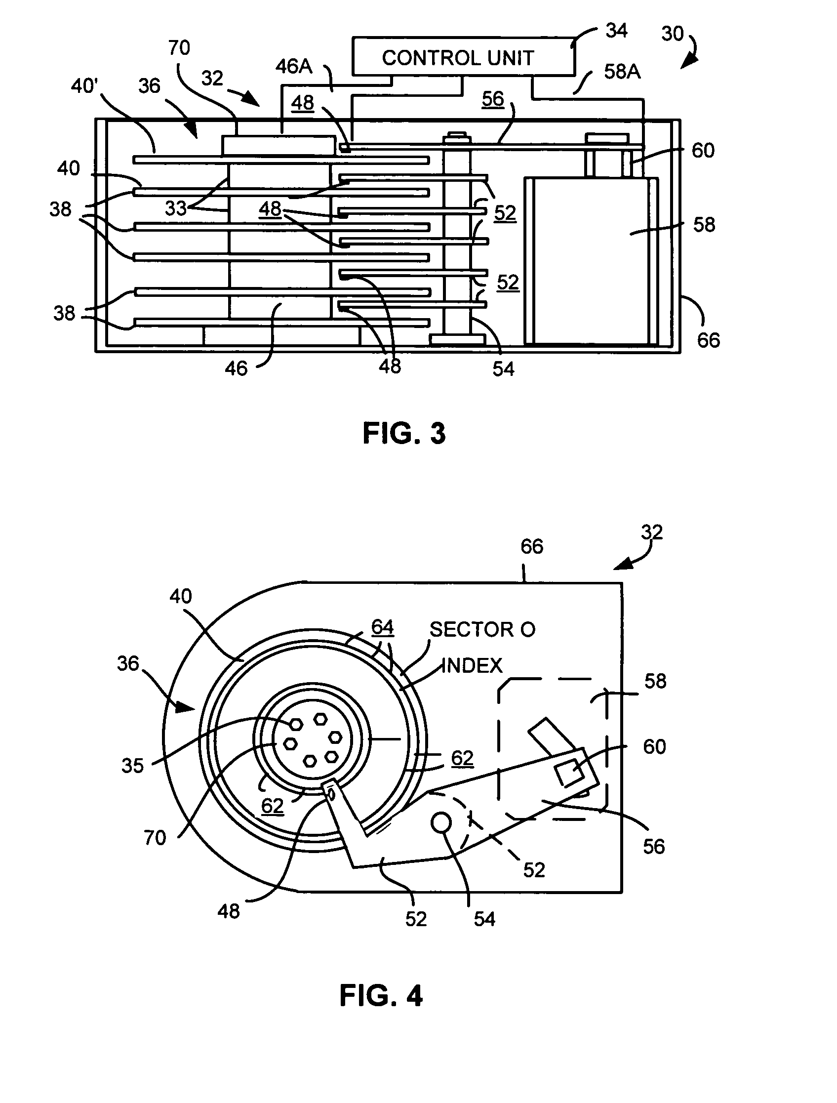
[0036]Referring now to the drawings wherein like reference numerals designate like or similar parts throughout the several views there is illustrated in FIG. 3 a cross-sectional diagram of parts of a data storage disk drive system 30 including a rigid magnetic disk drive unit generally designated as 32 and a control unit generally designated as 34. While a magnetic disk drive unit is illustrated, it should be understood that other mechanically moving memory configurations may be used. Unit 32 is illustrated in simplified form sufficient for an understanding of the present invention because the utility of the present invention is not limited to the details of a particular drive unit construction. After...


PUM

PropertyMeasurementUnit
mechanicalaaaaaaaaaa
densityaaaaaaaaaa
processabilityaaaaaaaaaa

Abstract

A composite disk-clamp assembly including a clamp or spacer of a resilient material coupled to a disk by injection molded plastic so that the clamp forms an integral portion of the disk itself.

Description

FIELD OF THE INVENTION[0001]The present invention relates to disk drive components, and more particularly, this invention relates to a disk assembly having an integral clamp and / or spacer.BACKGROUND OF THE INVENTION[0002]A typical disk drive storage system includes one or more magnetic disks which are mounted for co-rotation on a hub or spindle. A typical disk drive also includes a transducer supported by a hydrodynamic bearing which flies above each magnetic disk. The transducer and the hydrodynamic bearing are sometimes collectively referred to as a data head or a product head. A drive controller is conventionally used for controlling the disk drive based on commands received from a host system. The drive controller controls the disk drive to retrieve information from the magnetic disks and to store information on the magnetic disks. An electromechanical actuator operates within a negative feedback, closed-loop servo system to move the data head radially or linearly over the disk ...

Claims


Application Information

Patent Timeline
Patent Type & Authority Patents(United States)
IPC IPC(8): G11B17/028G11B23/03B29C45/14G11B17/08G11B23/00G11B25/04
CPCB29C45/14311B29C45/14491G11B23/0035G11B25/043B29L2017/003
Inventor FELISS, NORBERT A.GILLIS, DONALD RAYWOLTER, REINHARD F.
Owner HITACHI GLOBAL STORAGE TECH NETHERLANDS BV
Why Eureka
Try Eureka