Multi-table branch prediction circuit for predicting a branch's target address based on the branch's delay slot instruction address

a branch prediction circuit and delay slot technology, applied in the direction of computation using denominational number representation, instruments, program control, etc., can solve the problems of remarkably degrading processing efficiency, invalidating a plurality of subsequent instructions, and reducing processing capacity

Inactive Publication Date: 2008-11-04
KK TOSHIBA
View PDF8 Cites 2 Cited by
  • Summary
  • Abstract
  • Description
  • Claims
  • Application Information

AI Technical Summary

Benefits of technology

[0019]FIG. 5 is a diagram showing the operation during generation of a branching instruction in a ...

Problems solved by technology

Therefore, an ineffective cycle is generated, and this degrades capabilities.
This invalidates a plurality of subsequent instructions which have entered the pipeline in and after a delay slot.
Therefore, processing efficiency is remarkably degraded.
However, when the branch table is constituted of a large-capacity memory, it takes several cycles to access the branch table.
However, even when the branch predic...

Method used


Image

  • Multi-table branch prediction circuit for predicting a branch's target address based on the branch's delay slot instruction address
  • Multi-table branch prediction circuit for predicting a branch's target address based on the branch's delay slot instruction address
  • Multi-table branch prediction circuit for predicting a branch's target address based on the branch's delay slot instruction address

Examples


Embodiment Construction

[0022]An embodiment of the present invention will be described hereinafter with reference to the drawings.

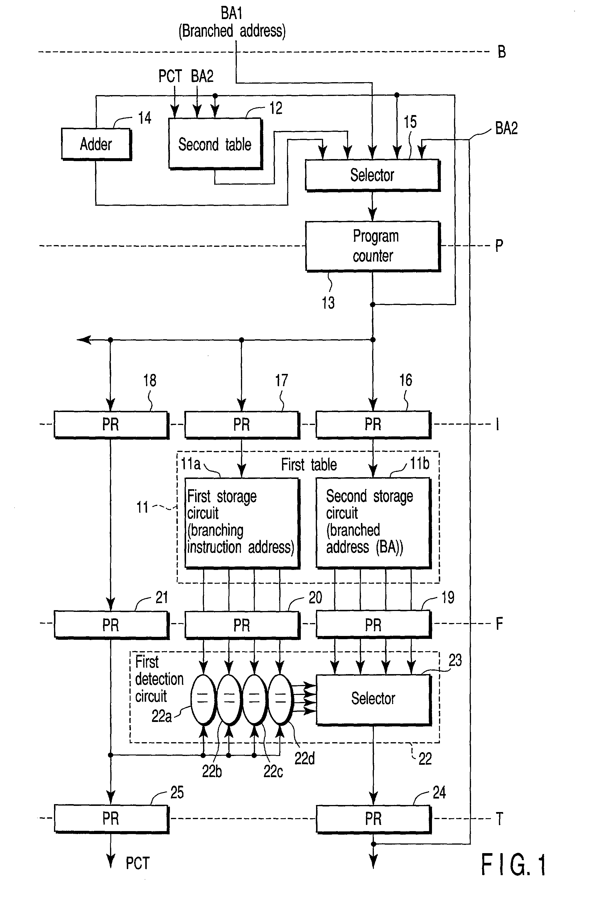
[0023]FIG. 1 shows a branch prediction circuit according to the embodiment of the present invention. The branch prediction circuit has a first table 11 as a first storage unit, and a second table 12 as a second storage un it. The first table 11 is a large-capacity memory which is constituted, for example, of a static RAM (SRAM) and which has, for example, 1024 entries. The second storage unit is a small-capacity and high-speed memory which is constituted, for example, of a flip-flop circuit and which has, for example, about four entries. In FIG. 1, a concrete constitution regarding the writing of information with respect to the first and second tables 11, 12 is omitted.

[0024]The branch prediction circuit is constituted of a pipeline which has, for example, five stages B to T. The first stage B is a stage for starting, for example, branch prediction, the second stage P is a progr...


PUM


Abstract

A first storage unit stores an address of a branching instruction and a branched address. A first detector detects whether or not an instruction of the present address has previously been branched from an output of the first storage unit. When the first detector detects previous branching of the instruction of the present address, the second storage unit stores the branched address corresponding to the address of the instruction to be executed following the branching instruction. When a second detector detects an output of a program counter as the address of the instruction to be executed following the branching instruction, the second storage unit outputs the branched address.

Description

CROSS-REFERENCE TO RELATED APPLICATIONS[0001]This application is based upon and claims the benefit of priority from the prior Japanese Patent Application No. 2002-060952, filed Mar. 6, 2002, the entire contents of which are incorporated herein by reference.BACKGROUND OF THE INVENTION[0002]1. Field of the Invention[0003]The present invention relates to a branch prediction circuit of a microprocessor for executing, for example, pipeline processing.[0004]2. Description of the Related Art[0005]In a microprocessor for performing pipeline processing, a branching instruction which changes the flow disturbs the pipeline processing. Therefore, an ineffective cycle is generated, and this degrades capabilities. Particularly, a microprocessor whose operation frequency exceeds a GHz has a multilayered pipeline. Therefore, in the microprocessor, ten or more cycles are required from when the instruction is fetched and recognized as the branching instruction until a branched address is calculated.[...

Claims


Application Information

Patent Timeline
IPC IPC(8): G06F9/00G06F9/38
CPCG06F9/3806
Inventor MORI, JUNJIGOTO, HARUTAKA
Owner KK TOSHIBA
Why Eureka
Try Eureka