
Dynamic cluster database architecture

a database and dynamic technology, applied in the field of computing systems, can solve problems such as system efficiency problems, shared disk architectures with potential scalability problems, and database systems that require computational resources or availability requirements that cannot be achieved by a single computer, and achieve the effect of improving the efficiency of database management system operations

Inactive Publication Date: 2008-11-04
INT BUSINESS MASCH CORP
View PDF35 Cites 11 Cited by
  • Summary
  • Abstract
  • Description
  • Claims
  • Application Information

AI Technical Summary

Benefits of technology

The present invention provides an improved method and system for accessing data in a database management system on a computer cluster. The system includes a set of database manager components that manage resources on the cluster of computers. The components include resource manager code for managing system resources, lock manager code for managing locks on data nodes, and architecture manager code for specifying logical connections between data nodes. The system also includes a computer-implemented method for migrating data nodes from a shared disk architecture to a sharednothing architecture or vice versa. The invention allows for balancing workload in the cluster and sharing available resources between computers. Overall, the invention provides a more efficient and effective way to manage data in a distributed database management system on a computer cluster.

Problems solved by technology

Database systems often require computational resources or availability requirements that cannot be achieved by a single computer.
However, the shared disk architecture has potential scalability problems because such a system requires a distributed lock manager for the database.
When such a system is scaled up, workloads that require a significant amount of lock communication between cluster machines will cause efficiency problems for the system.

Method used


Image

  • Dynamic cluster database architecture
  • Dynamic cluster database architecture
  • Dynamic cluster database architecture

Examples


Embodiment Construction

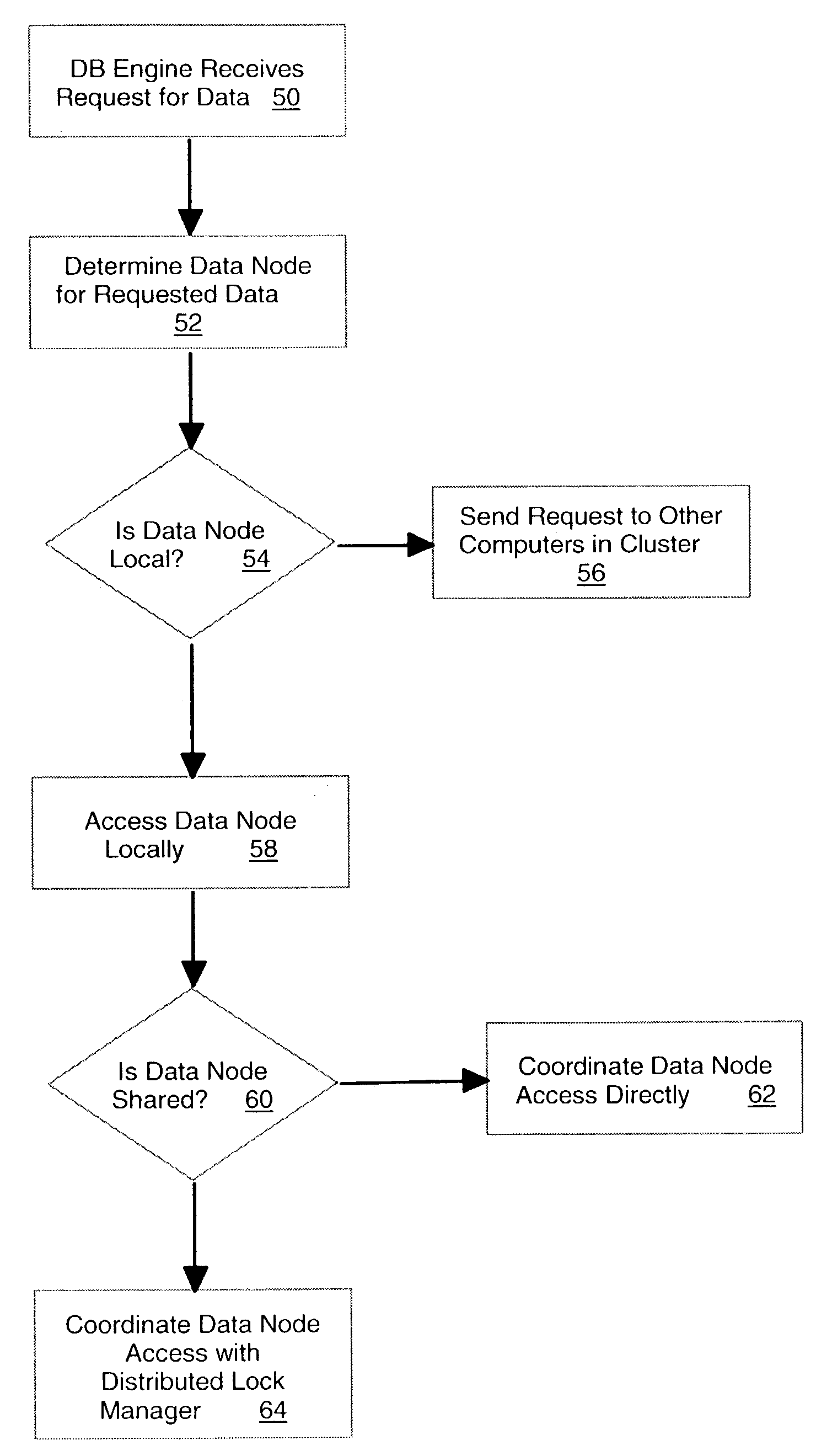
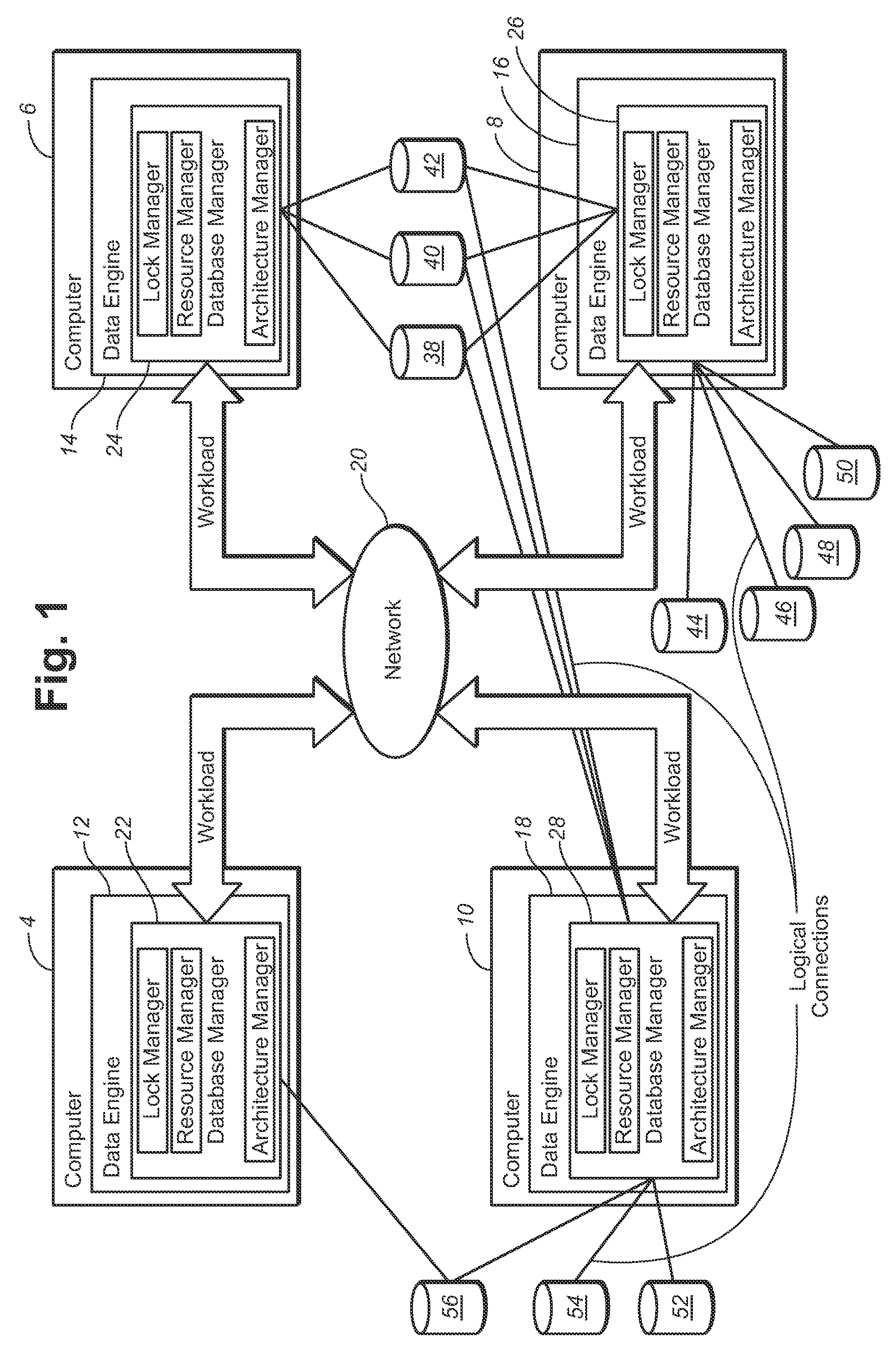
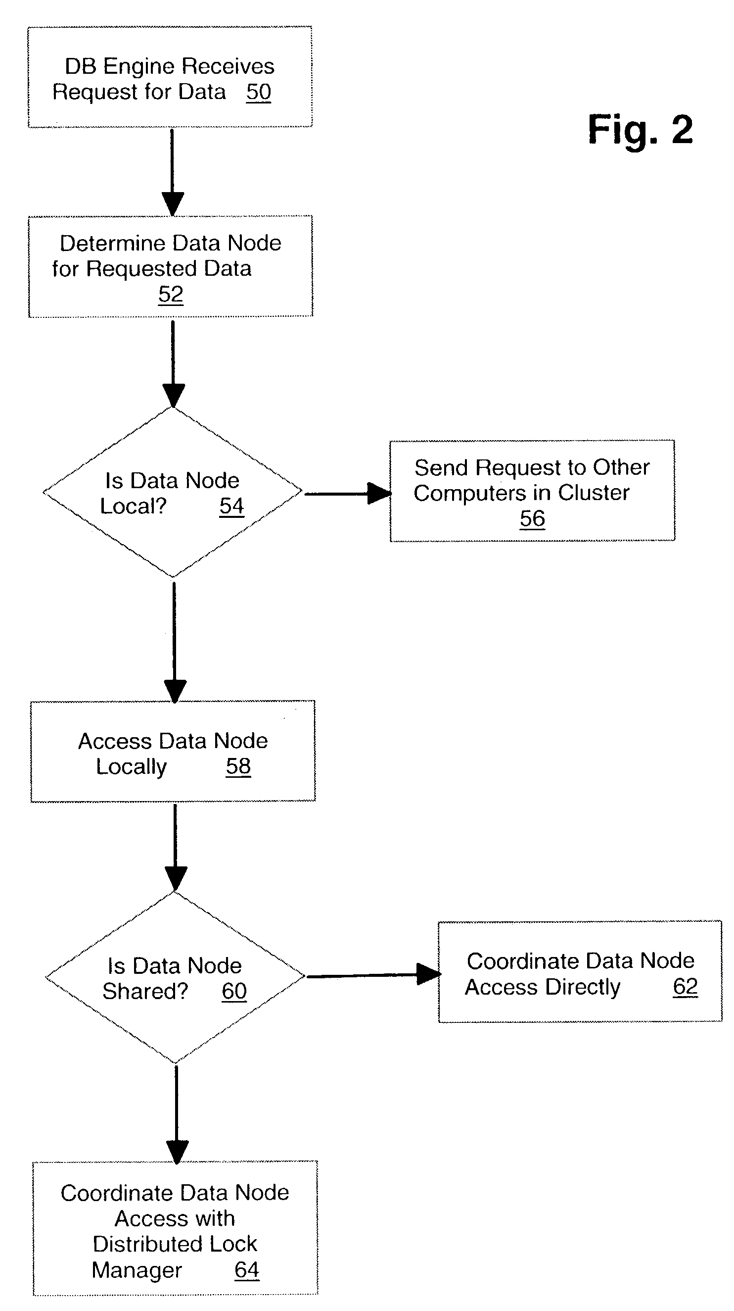
[0036]FIG. 1 shows, in a block diagram format, an example illustrating a computer cluster upon which is implemented a database management system according to the preferred embodiment. FIG. 1 shows computers 4, 6, 8, 10 that collectively represent a cluster of computers usable by a database system. The database engine for the system of the preferred embodiment is distributed and shown in FIG. 1 by database engine components 12, 14, 16, 18 on computers 4, 6, 8, 10, respectively. The database engine components are able to execute database tasks on their respective computers 4, 6, 8, 10 forming the cluster, as well as to carry out the functions described below that relate to the operation of the distributed database system in the cluster. Each of computers 4, 6, 8, 10 in the cluster shown in FIG. 1 is connected by network 20.

[0037]The preferred embodiment includes a distributed database manager layer that is shown collectively in FIG. 1 by distributed database managers 22, 24, 26, 28. T...


PUM


Abstract

A distributed database management system implemented on a cluster of computers. The cluster including disks organized as data nodes. The data nodes being locally connected to one or more computers in the cluster. The distributed database management system includes a distributed database manager layer having a lock manager, a resource manager, and an architecture manager. The lock manager serializes access to the data nodes in the cluster. The resource manager maintains a data representation of the resources of each computer in the cluster and makes the data available to other computers in the cluster to facilitate access to the resources by the other computers. The architecture manager defines logical ownership relationships between data nodes and computers in the cluster to permit the architecture of the database to be dynamically reconfigured to provide improved performance.

Description

FIELD OF THE INVENTION[0001]This invention generally relates to computing systems and in particular to an architecture for clustering in database systems.BACKGROUND OF THE INVENTION[0002]Database systems often require computational resources or availability requirements that cannot be achieved by a single computer. In such cases, a number of machines can be arranged in a cluster to permit a single database task to be carried out by the cluster of machines rather than by a single machine. In terms of scalability, clusters of machines provide for a potentially more attractive model for database processing in comparison with alternatives such as SMP systems. In addition, cluster architectures for database systems also provide for potentially higher availability than is possible with a single machine. For these reasons, cluster architectures for database systems are used in different database management systems that are commercially available. In such systems, there are two approaches t...

Claims


Application Information

Patent Timeline
Patent Type & Authority Patents(United States)
IPC IPC(8): G06F7/00G06F17/30
CPCG06F17/30362G06F17/30575G06F16/27G06F16/2343Y10S707/99931Y10S707/99953Y10S707/99938G06F16/278
Inventor WILDING, MARK F.HURAS, MATTHEW A.
Owner INT BUSINESS MASCH CORP
Learn More