
Moving apparatus and method of self-direction testing and self-direction correction thereof

a moving apparatus and self-direction correction technology, applied in the field of moving apparatus, can solve the problems of affecting accuracy and reliability, unexpected accidents or damage, additional cost, etc., and achieve the effect of simplifying design, reducing cost, and improving accuracy and reliability of direction navigation of moving apparatus

Active Publication Date: 2008-10-28
IND TECH RES INST
View PDF8 Cites 5 Cited by
  • Summary
  • Abstract
  • Description
  • Claims
  • Application Information

AI Technical Summary

Benefits of technology

[0009]The present invention provides a method of self-direction testing and self-direction correction, applicable for a moving apparatus to enhance the accuracy and reliability of direction navigation.
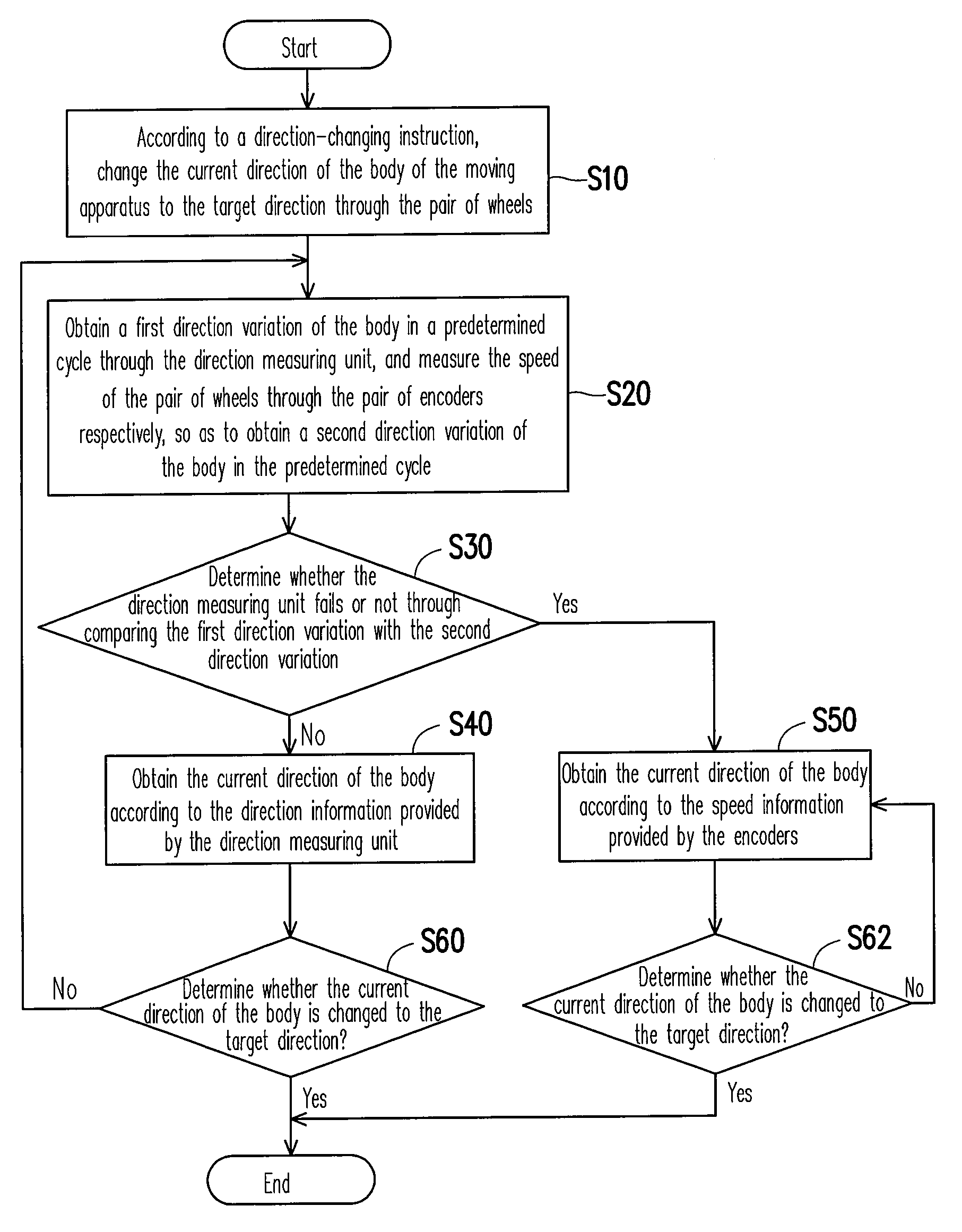
[0012]In the present invention, since whether the direction measuring unit is temporarily dysfunction is determined according to information of the speed provided by the encoders originally installed on the body to measure the wheel speed, the accuracy and reliability of the direction navigation of the moving apparatus can be improved through changing the internal arithmetic logic of the controller, without adding any new hardware devices or changing the existing hardware design architecture. Therefore, the present invention has the advantages of reducing the cost and simplifying the design.

Problems solved by technology

However, with regard to the moving apparatus using the electronic compass for direction navigation, it is an unavoidable problem that a magnetic field of a surrounding environment causes interferences to the electronic compass, thereby affecting the accuracy and reliability of the direction navigation of the moving apparatus, and thus possibly causing unexpected accidents or damages.
However, although the assistant direction measuring unit may correct a direction signal for the electronic compass, the gyroscope causes an additional cost, and the optical encoder not only increases the cost, but also it is complicated for being designed and integrated into the electronic compass.

Method used


Image

  • Moving apparatus and method of self-direction testing and self-direction correction thereof
  • Moving apparatus and method of self-direction testing and self-direction correction thereof
  • Moving apparatus and method of self-direction testing and self-direction correction thereof

Examples


Embodiment Construction

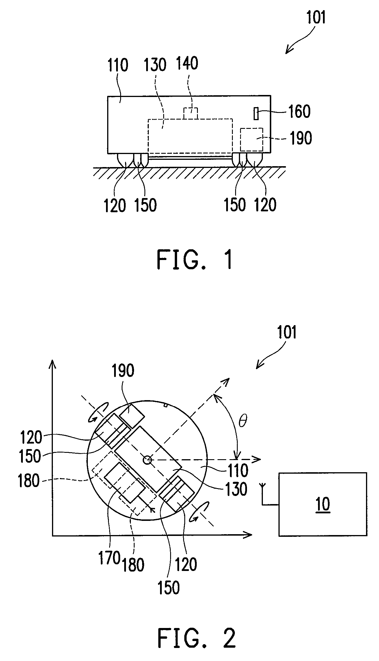
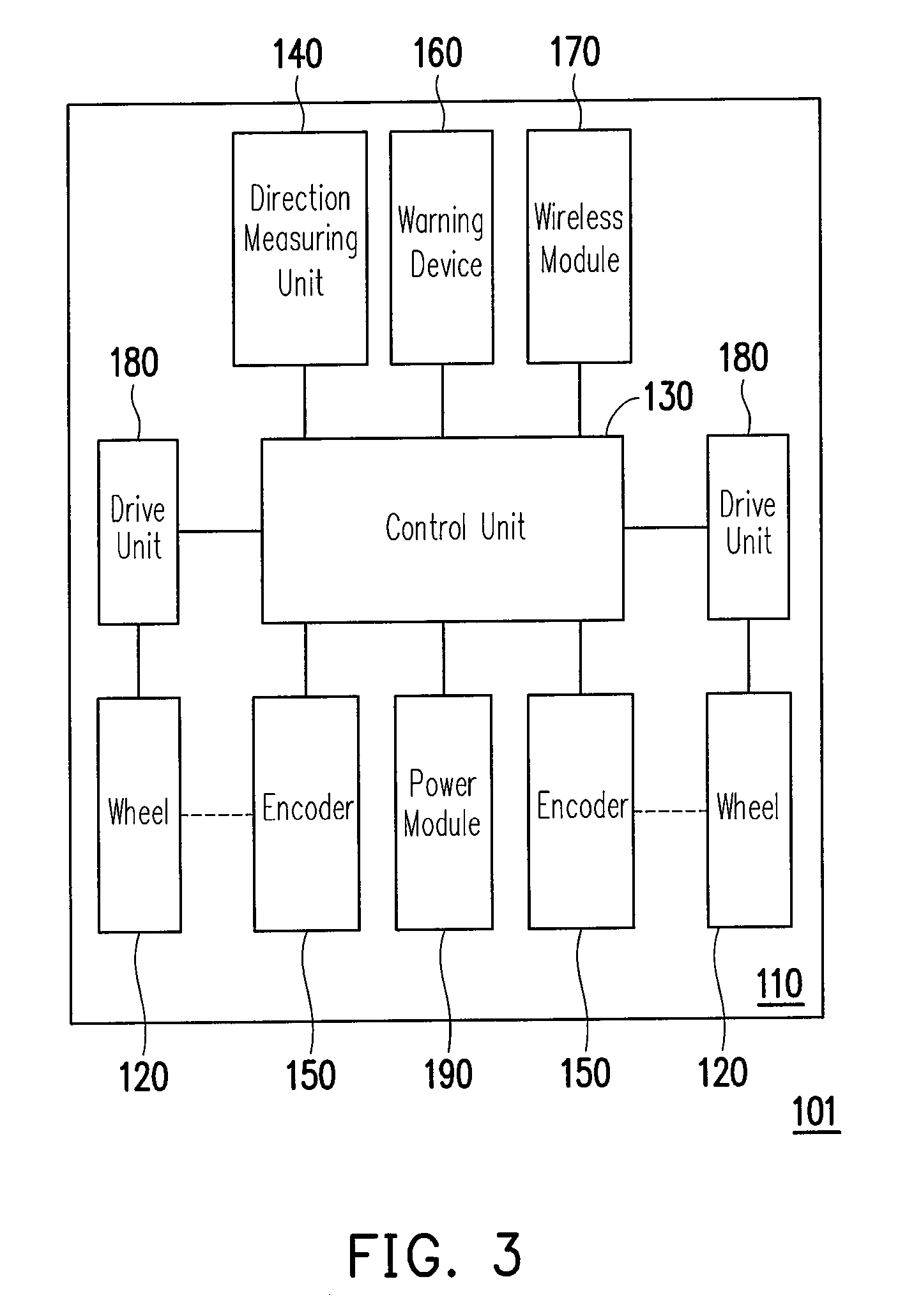
[0022]FIG. 1 is a side view of a moving apparatus according to an embodiment of the present invention, FIG. 2 is a top view of the moving apparatus in FIG. 1, and FIG. 3 is a block diagram of the moving apparatus in FIG. 1. Referring to FIGS. 1 to 3, the moving apparatus 101 in this embodiment includes a body 110 and a pair of wheels 120. The pair of the wheels 120 is installed on the body 110, for changing a direction of the body 110 and moving the body 110.

[0023]The moving apparatus 101 further includes a control unit 130 installed on the body 110. The moving apparatus 101 further includes a direction measuring unit 140 installed on the body 110 and coupled to the control unit 130, for measuring direction information of the body 110 and transmitting the direction information to the control unit 130, such that the control unit 130 obtains a first direction variation of the body 110 according to the direction information. In this embodiment, the direction measuring unit 140 may be a...


PUM


Abstract

A moving apparatus has a body, and has at least a pair of wheels, a control unit, a direction measuring unit and at least a pair of encoders installed on the body. The direction measuring unit coupled to the control unit measures the direction of the body, and the control unit obtains a first direction variation according to the direction information. The pair of encoders coupled to the control unit measure a speed of the pair of wheels, and the control unit obtains a second direction variation according to information of the speed. The control unit compares the first and second direction variations to determine whether the direction measuring unit is temporarily dysfunction. Based on the result of comparison, the control unit applies the information provided by the direction measuring unit or the pair of encoders to obtain the current direction of the body.

Description

CROSS-REFERENCE TO RELATED APPLICATION[0001]This application claims the priority benefit of Taiwan application serial no. 95149969, filed on Dec. 29, 2006. All disclosure of the Taiwan application is incorporated herein by reference.BACKGROUND OF THE INVENTION[0002]1. Field of the Invention[0003]The present invention relates to a moving apparatus. More particularly, the present invention relates to a moving apparatus and a method of self-direction testing and self-direction correction thereof.[0004]2. Description of Related Art[0005]In order to enable a moving apparatus to change its current direction to a target direction, various direction navigation technologies have been developed and applied in the moving apparatus. The moving apparatus mentioned herein refers to a robot that moves by wheels without a fixed track, such as, an automobile, a security robot that is capable of going on patrol automatically, and a vacuum cleaner robot that is capable of cleaning a room automatically...

Claims


Application Information

Patent Timeline
Patent Type & Authority Patents(United States)
IPC IPC(8): G01C22/00
CPCG01C21/005G05D1/0272G05D1/027
Inventor HUANG, HSUAN-KUANYU, HUNG-HSIUWANG, WEI-HANLIU, CHING-YI
Owner IND TECH RES INST
Learn More