
Electric switch

a technology of electric switch and switch body, which is applied in the direction of contact mechanism, electrical apparatus, contact, etc., can solve the problems of inability to produce reliable electrical contact and current-conducting connection

Active Publication Date: 2008-10-28
ZF FRIEDRICHSHAFEN AG
View PDF10 Cites 8 Cited by
  • Summary
  • Abstract
  • Description
  • Claims
  • Application Information

AI Technical Summary

Benefits of technology

The invention is an electrical switch with a unique contactor design that can self-clean and remove foreign particles from its surfaces. The contactor is made in a leaf spring shape and has a fastening area, a central deformation area, and an adjacent stiffened actuating area. The actuating member can be a reinforcing compression spring or a pivoting movement. The contact fingers move with their wide side onto the contact surfaces of the selective contact bodies, ensuring reliable switching behavior and self-cleaning of the switch. The arrangement of the contact fingers in pairs strengthens switch reliability due to their redundancy. The invention provides a simple yet effective solution for electrical switches that can operate under unfavorable environmental conditions.

Problems solved by technology

In the known switch in accordance with DE 44 20 665 B4, it is disadvantageous that the current-conducting connection requires a plurality of components starting from the fixed common contact body via the helical spring and the contact plate up to the contact finger and in addition requires the sliding body of the contactor for holding or positioning these components.
In addition, the aforesaid special switching bodies must be placed on the switching free end of the elastically deformable contactor in accordance with EP 1 533 823 A1, likewise on the surfaces of the opposing areas of first and second selective contactor, which surfaces cooperate therewith; otherwise it is not possible to produce a reliable electrical contact.

Method used


Image

  • Electric switch
  • Electric switch
  • Electric switch

Examples


first embodiment

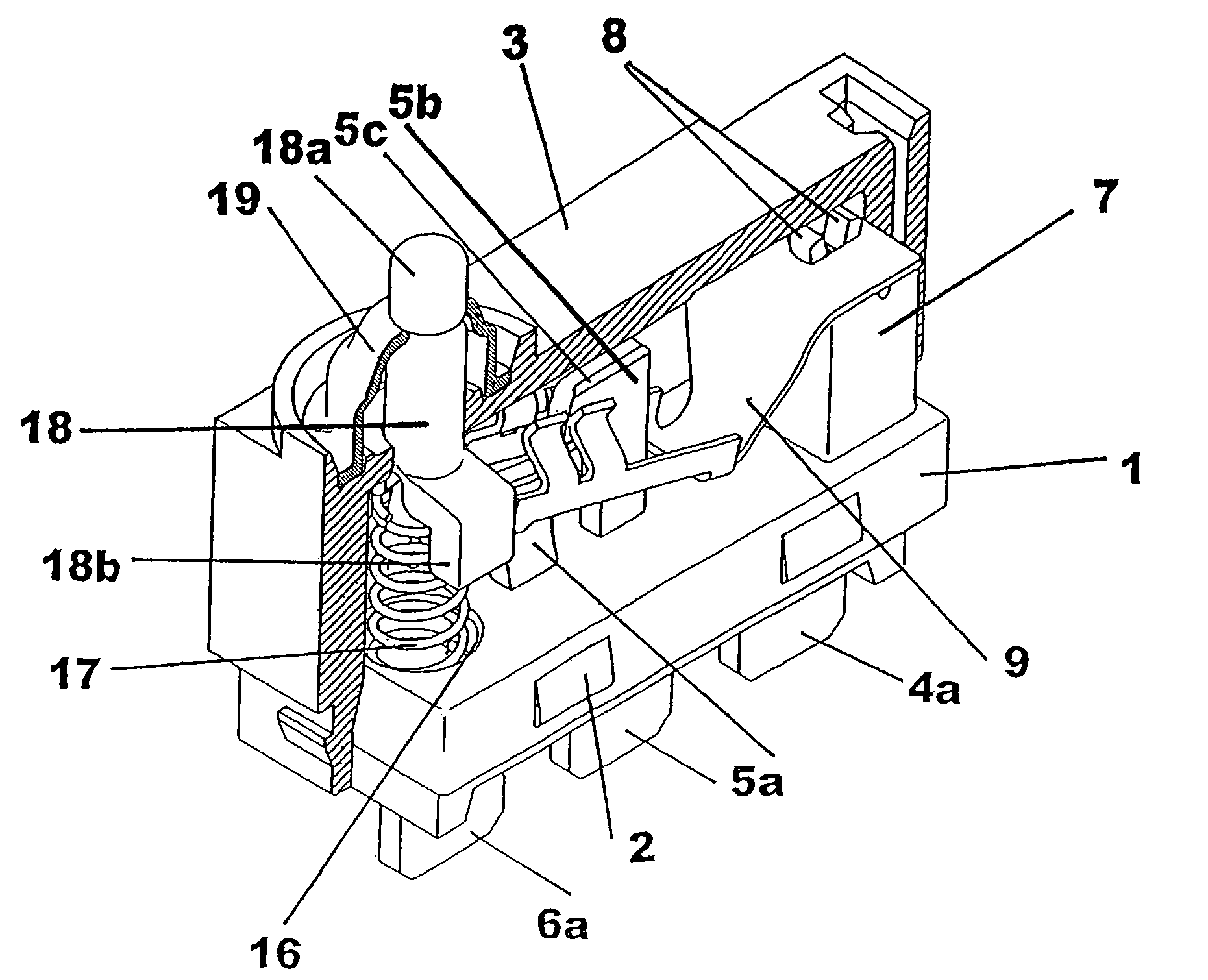
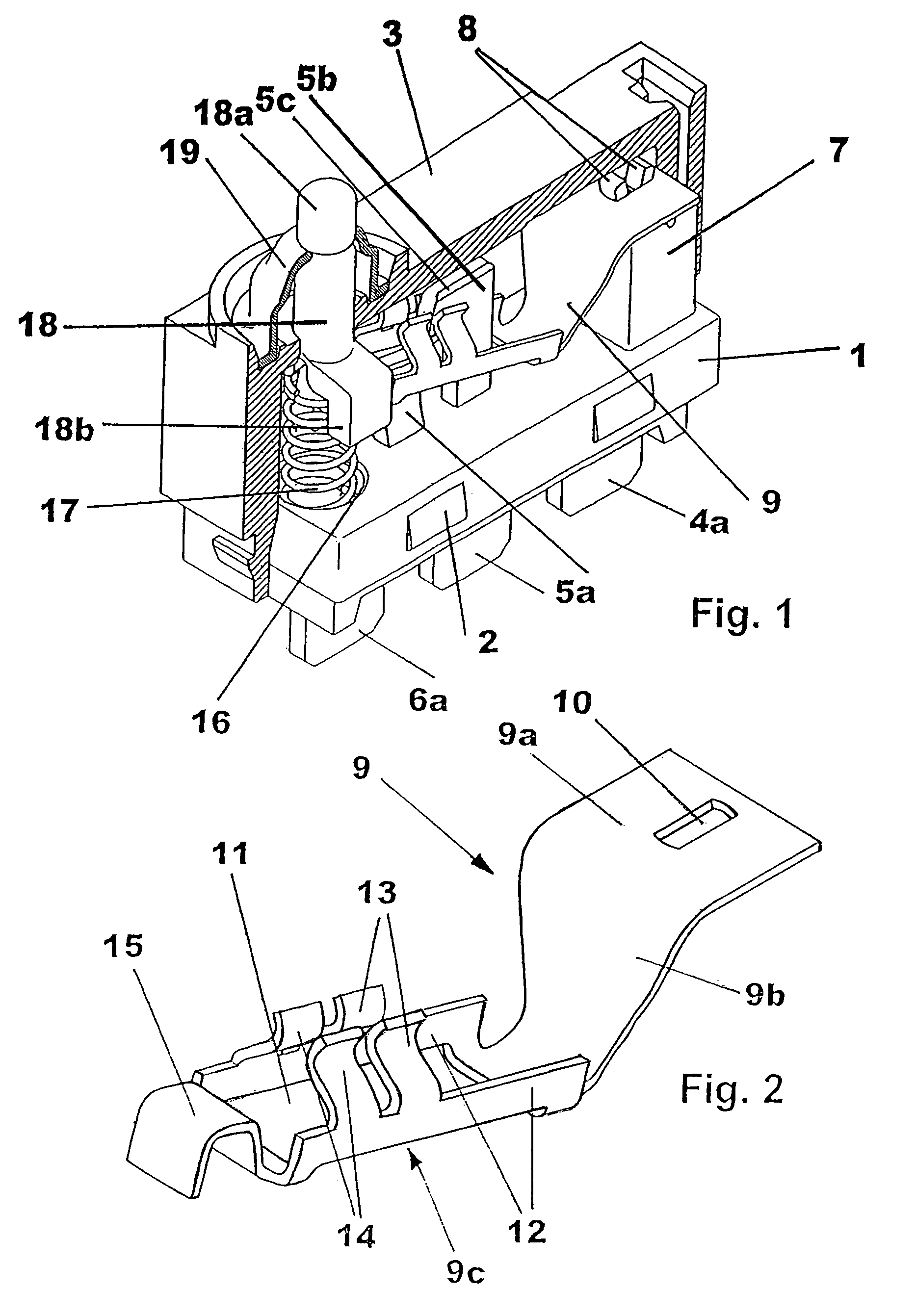
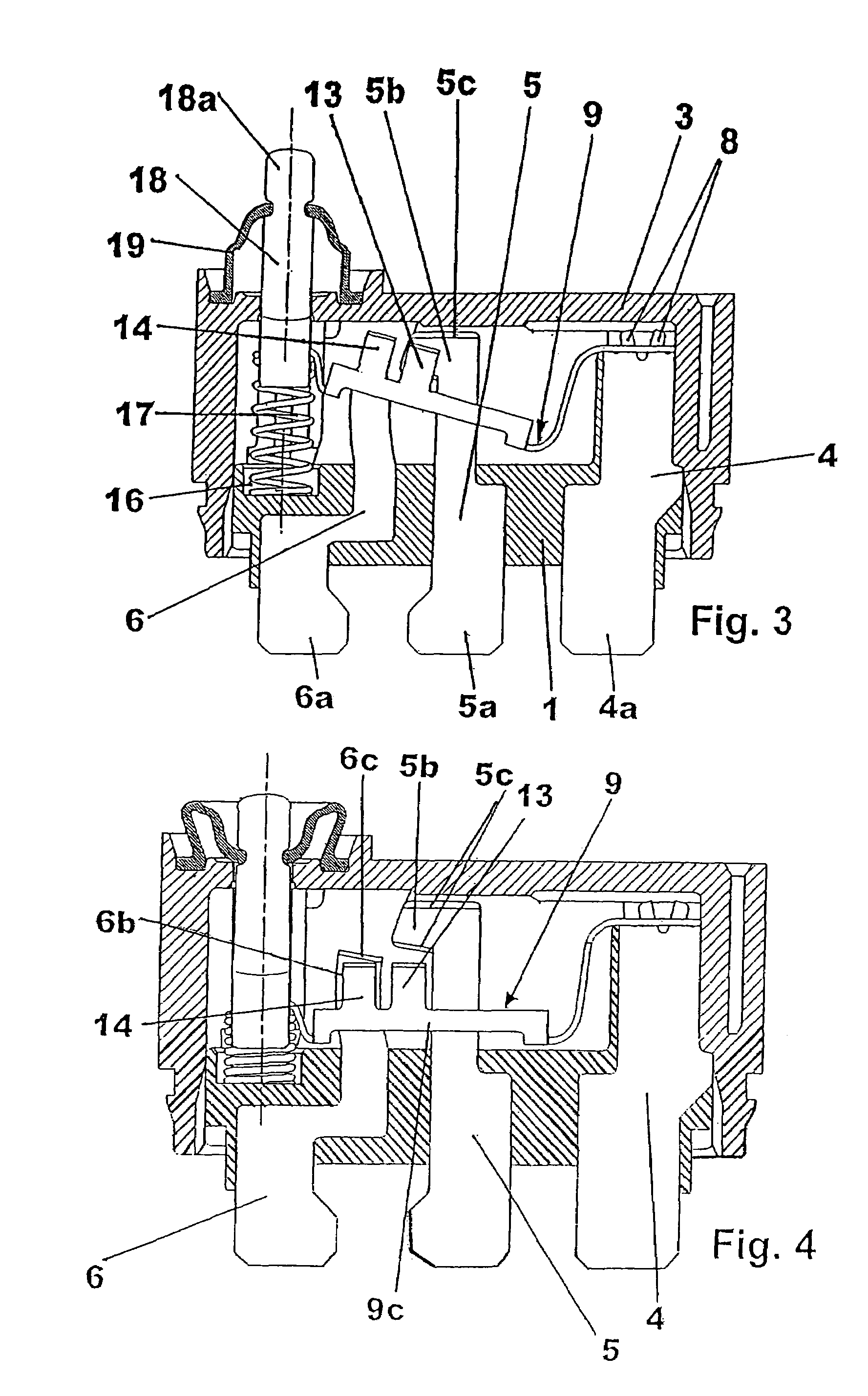
[0032]FIGS. 1 through 4 depict the electrical switch in accordance with the invention. The switch has a housing comprising a base 1 that has fastening projections 2 for fastening a cover 3. Set in the insulating material of the base 1 are three contact bodies, specifically a common contact body 4, a first selective contact body 5, and a second selective contact body 6. The contact bodies 4, 5, and 6 have a flat plate-like configuration and have different contours (see FIGS. 3 and 4).

[0033]A connector contact 4a is embodied at the bottom of the common contact body 4, likewise a connector contact 5a is embodied at the bottom of the first selective contact body 5 and a connector contact 6a is embodied at the bottom of the second selective contact body 6. The function of the switch is to connect in an electrically conducting manner either to the connector contact 5a or to the connector contact 6a depending on the switching position of the connector contact 4a.

[0034]A contactor 9 made o...

third embodiment

[0047]FIGS. 9 through 11 depict the inventive the electrical switch. Essential parts thereof have already been described using FIGS. 1 through 4 and are labeled with the same reference numbers. In this case, as well, there is a common contact body 31 having a connector contact 31a as well as first and second selective contact bodies 32, 33 with connector contacts 32a and 33a. Anchoring apertures are labeled 31b and 33c, and these are used to fasten the common contact body 31 and the second contact body 33 to the insulating material of the base 1. In contrast to the exemplary embodiments already described, the first and second contact bodies 32 and 33 no longer retain the continuous flat, plate-like shape. On the contrary, the areas of the two selective contact bodies 32, 33 that form the contact surfaces 32b and 33b are bent outward approximately 90° out of the basic flat shape of the selective contact body; thus they run transverse to the longitudinal orientation of the contactor 3...


PUM


Abstract

An electrical switch has a common contact body and a first selective contact body and a second selective contact body. A contactor is connected mechanically and in an electrically conducting manner to the common contact body. The contactor comprises an elastic, electrically conducting material. It is formed originating from the basic form of a leaf spring into a multifunctional part having a clamping area, a deformation area and a stiffened actuating area. The pre-tension of the contactor causes the contact fingers to be positioned against the contact surfaces of the first selective contact body. Pressure on the actuating area elastically deforms the contactor, and the actuating area pivots with the contact fingers so that the contact fingers switchingly enclose the contact surfaces of the second selective contact body.

Description

BACKGROUND OF THE INVENTION[0001]The invention relates to an electrical switch in which a common contact body and a first selective contact body and a second selective contact body are provided in a housing. A movable contactor that can be moved outside of the housing against spring force produces the electrically conducting connection between the common contact body and either the first or the second selective contact body. A switch of this type is known for instance from DE 44 20 665 B4.[0002]In this known switch, the contact surfaces of the first selective contact body and of the second selective contact body are set in a wall of the switch housing. The contactor is a sliding body that is provided with an actuating member that projects from the housing. Added to the sliding body is a contact plate that has a projecting contact finger. The contactor is pressed into its final position by a compression spring in the form of a helical spring. The helical spring produces the electrica...

Claims


Application Information

Patent Timeline
Patent Type & Authority Patents(United States)
IPC IPC(8): H01H13/12
CPCH01H1/42H01H13/12H01H13/52H01H2001/0005
Inventor BAUER, GUENTERRUFF, EDUARD
Owner ZF FRIEDRICHSHAFEN AG
Learn More