
Lamp thermal management system

a technology for managing systems and lamps, applied in lighting devices, transportation and packaging, lighting and heating equipment, etc., can solve problems such as poor conduction between the lamp and the external luminaire surface, exacerbate heat related failures, and basic problems

Active Publication Date: 2008-10-21
ABL IP HLDG
View PDF26 Cites 74 Cited by
  • Summary
  • Abstract
  • Description
  • Claims
  • Application Information

AI Technical Summary

Problems solved by technology

In any luminaire design, the heat generated by the lamp can cause problems related to the basic function of the lamp and luminaire.
Traditional means of providing electrical and mechanical contact between lamp and luminaire provide poor means for conduction to occur between the lamp and external luminaire surfaces.
In many cases, the luminaire may be enclosed, which further exacerbates heat related failures.
For example, in luminaires with electronic ballasts and components, the excessive heat can shorten the life of the electronic components causing premature failure of the lighting system.
Open luminaires can provide good convective energy transfer, but due to limitations of luminaire construction or other application requirements, cannot always provide adequate cooling of the luminaire.

Method used


Image

  • Lamp thermal management system
  • Lamp thermal management system
  • Lamp thermal management system

Examples


Embodiment Construction

[0017]The present invention can be understood more readily by reference to the following detailed description, examples, drawings, and claims, and their previous and following description. However, before the present devices, systems, and / or methods are disclosed and described, it is to be understood that this invention is not limited to the specific devices, systems, and / or methods disclosed unless otherwise specified, as such can, of course, vary. It is also to be understood that the terminology used herein is for the purpose of describing particular aspects only and is not intended to be limiting.

[0018]The following description of the invention is provided as an enabling teaching of the invention in its best, currently known embodiment. To this end, those skilled in the relevant art will recognize and appreciate that many changes can be made to the various aspects of the invention described herein, while still obtaining the beneficial results of the present invention. It will als...


PUM


Abstract

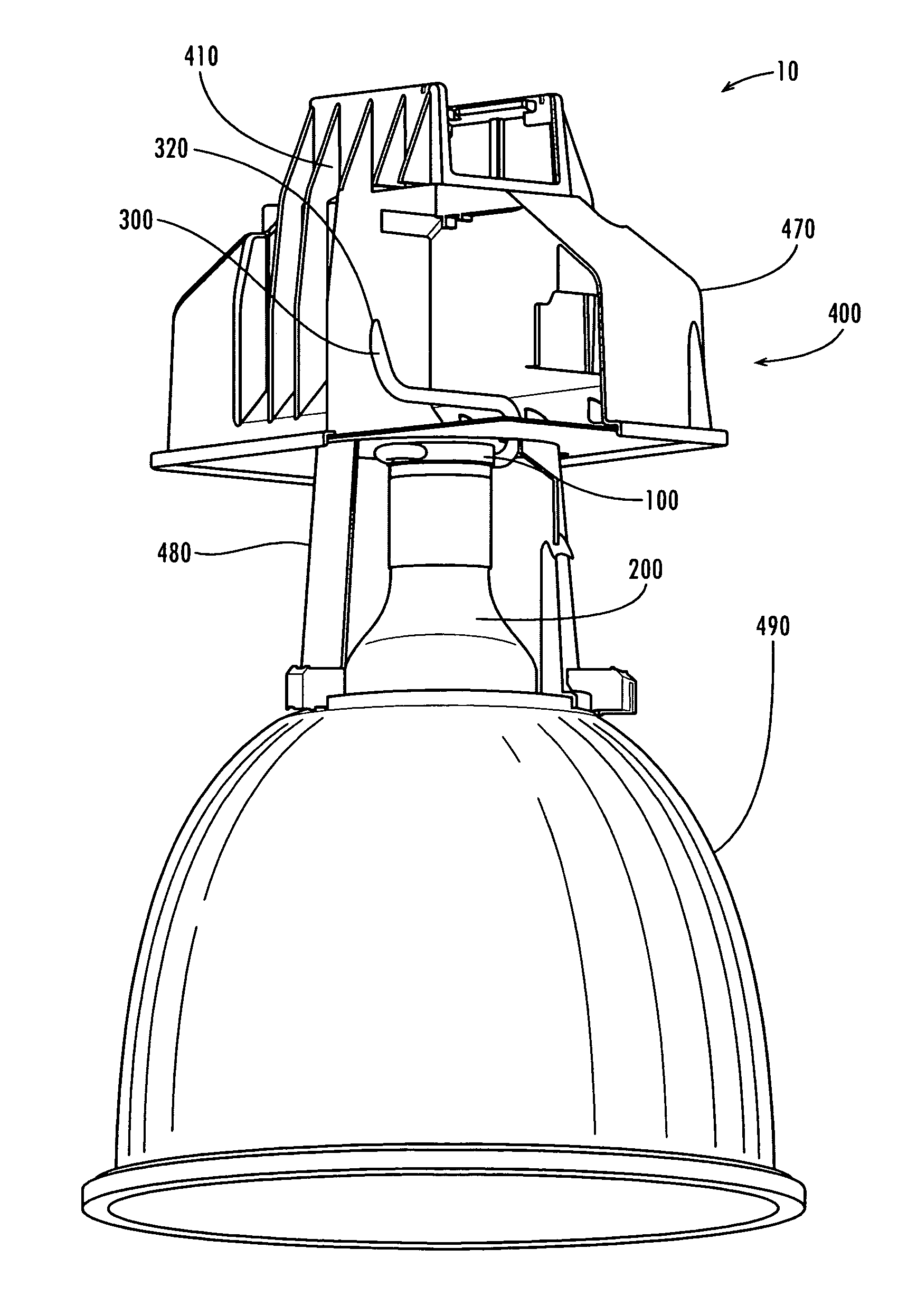
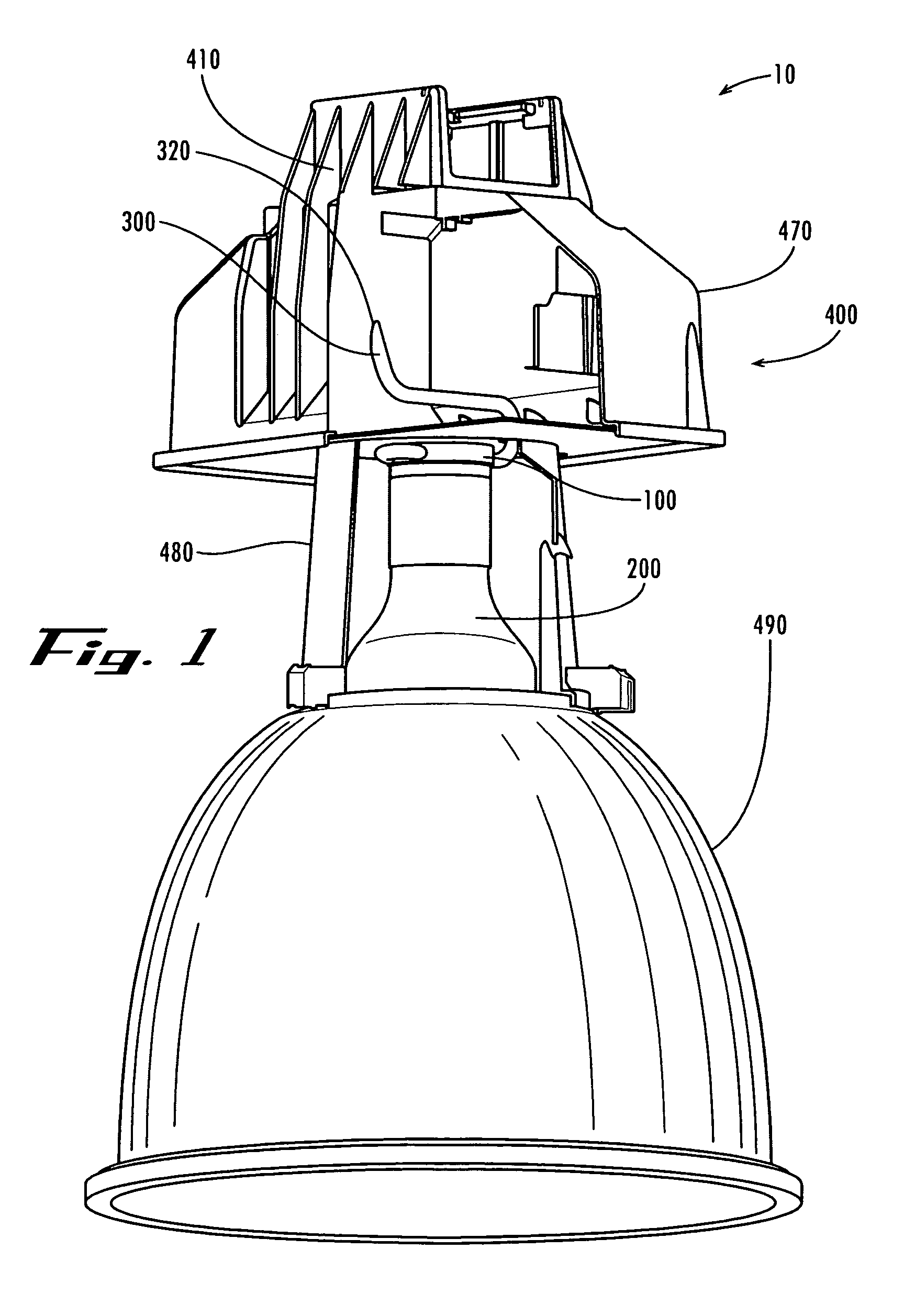
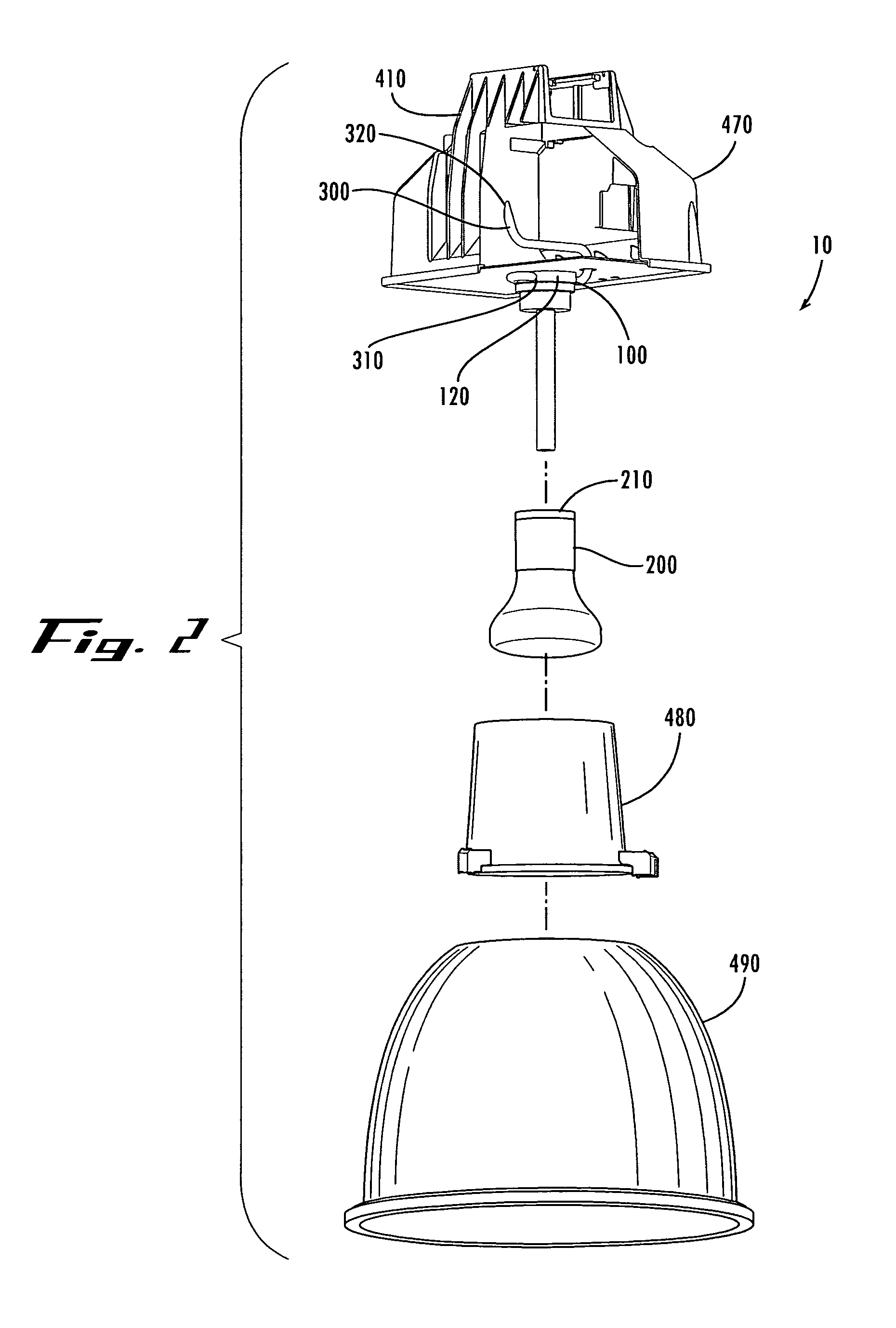
The invention relates to a thermal management system for a lamp. The system comprises a lamp socket that comprises a socket body. The thermal assembly is in thermal communication with the socket body to form a thermal circuit between the lamp and the thermal assembly for dissipating heat generated by the lamp.

Description

FIELD OF THE INVENTION[0001]The present invention pertains to a thermal management system for a lamp. More specifically, the invention relates to an apparatus and method for dissipating heat from a variety of lamp types.BACKGROUND OF THE INVENTION[0002]There are a variety of lamps used in the lighting industry. Some examples are high intensity discharge (HID), fluorescent, LED, induction and incandescent. Each of these lamps emits energy in the form of radiant energy and heat in various amounts. For example, a 400 watt metal halide lamp converts approximately 110 watts to visible energy, 20 watts to UV energy, 70 watts to IR energy, while the remaining 200 watts of energy is converted to heat and dissipated to the surrounding environment via conduction through the lamp base and convection off the glass envelope.[0003]A significant amount of energy is converted to heat by the lamp. In any luminaire design, the heat generated by the lamp can cause problems related to the basic functio...

Claims


Application Information

Patent Timeline
Patent Type & Authority Patents(United States)
IPC IPC(8): F21V29/00
CPCF21V23/02F21V29/76F21V29/006F21V29/004F21V29/51F21V29/763
Inventor DOROGI, MICHAEL JAY
Owner ABL IP HLDG
Learn More