
Fiber laser beam processing apparatus

a laser beam processing and fiber laser technology, applied in the field of can solve the problems of fiber laser tend to occur degradation poor laser beam processing reproducibility and reliability, unstable laser output of conventional fiber laser beam processing equipment, etc., to improve the stability of fiber laser output, improve the reproducibility and reliability of laser beam processing, and improve the effect of laser oscillation performance degradation

Inactive Publication Date: 2008-10-14
MIYACHI TECHNOS CORP
View PDF6 Cites 29 Cited by
  • Summary
  • Abstract
  • Description
  • Claims
  • Application Information

AI Technical Summary

Benefits of technology

[0007]The present invention was conceived in view of the above conventional technical problems and an object of the present invention is to provide a fiber laser beam processing apparatus that improves the stability of the fiber laser output and, as a result, improves the reproducibility and the reliability of the laser beam processing.
[0008]Another object of the present invention is to provide a fiber laser beam processing apparatus adapted to prevent degradation of the laser oscillation performance and damages and degradation of the oscillating optical fiber by reducing influences exerted from disturbances at the processing site on the fiber laser or the fiber laser oscillator.
[0011]In the fiber laser beam processing apparatus of the present invention, the laser output (power) of the fiber laser beam generated by the oscillating fiber or the fiber laser oscillator is normally stabilized accurately corresponding to the desired reference value or the desired reference waveform according to the real-time power feedback control. Therefore, even when any of variation of the power source unit output, degradation of the pumping unit, shifting of wavelength, etc., has occurred, the arbitrary control of the waveform can be executed stably and accurately and the reproducibility and the reliability of the laser beam processing can be improved.
[0012]According to a preferred aspect of the present invention, a fiber laser beam generated by an oscillating fiber or a fiber laser oscillator is injected into a transmitting optical fiber and is transmitted to a laser beam irradiating unit at a processing site. According to this configuration, the beam mode and the laser output of the fiber laser beam are both stable. Therefore, the convergence onto the transmitting optical fiber can be excellent, and the injection and the irradiating numerical apertures (NAs) can be stable. Therefore, high-precision and high-efficiency fiber transmission is enabled and the quality of remote laser beam processing can be improved. In addition, the oscillating optical fiber or the fiber laser oscillator can be placed away from the processing site and, therefore, the fiber laser oscillator can be protected against the disturbances such as the heat, vibrations, ambient light, etc.
[0014]According to the fiber laser beam processing apparatus of the present invention, based on the above configuration and actions, the stability of the fiber laser output can be improved and, as a result, the reproducibility and the reliability of laser beam processing can be improved and, in addition, by reducing influences exerted from the disturbances at the processing site on the fiber laser or the fiber laser oscillator, degradation of the laser oscillation performance and damages and degradation of the oscillating optical fiber can be prevented.

Problems solved by technology

However, the conventional fiber laser beam processing apparatus has an aspect of unstable laser output thereof due to an influence of degradation of the excitation LD, a wavelength shift, etc.
Therefore, the reproducibility and the reliability of the laser beam processing are poor.
Because the fiber laser is also vulnerable to influences of the heat, vibrations, ambient light, etc., problems have also arisen that the fiber laser tend to occur degradation of the laser oscillation performance, damage, degradation, etc., of components thereof (the optical fiber for oscillation, optical resonator, etc.).

Method used


Image

  • Fiber laser beam processing apparatus
  • Fiber laser beam processing apparatus
  • Fiber laser beam processing apparatus

Examples


Embodiment Construction

[0017]Description will be given below for a preferred embodiment of the present invention referring to the accompanying drawings.

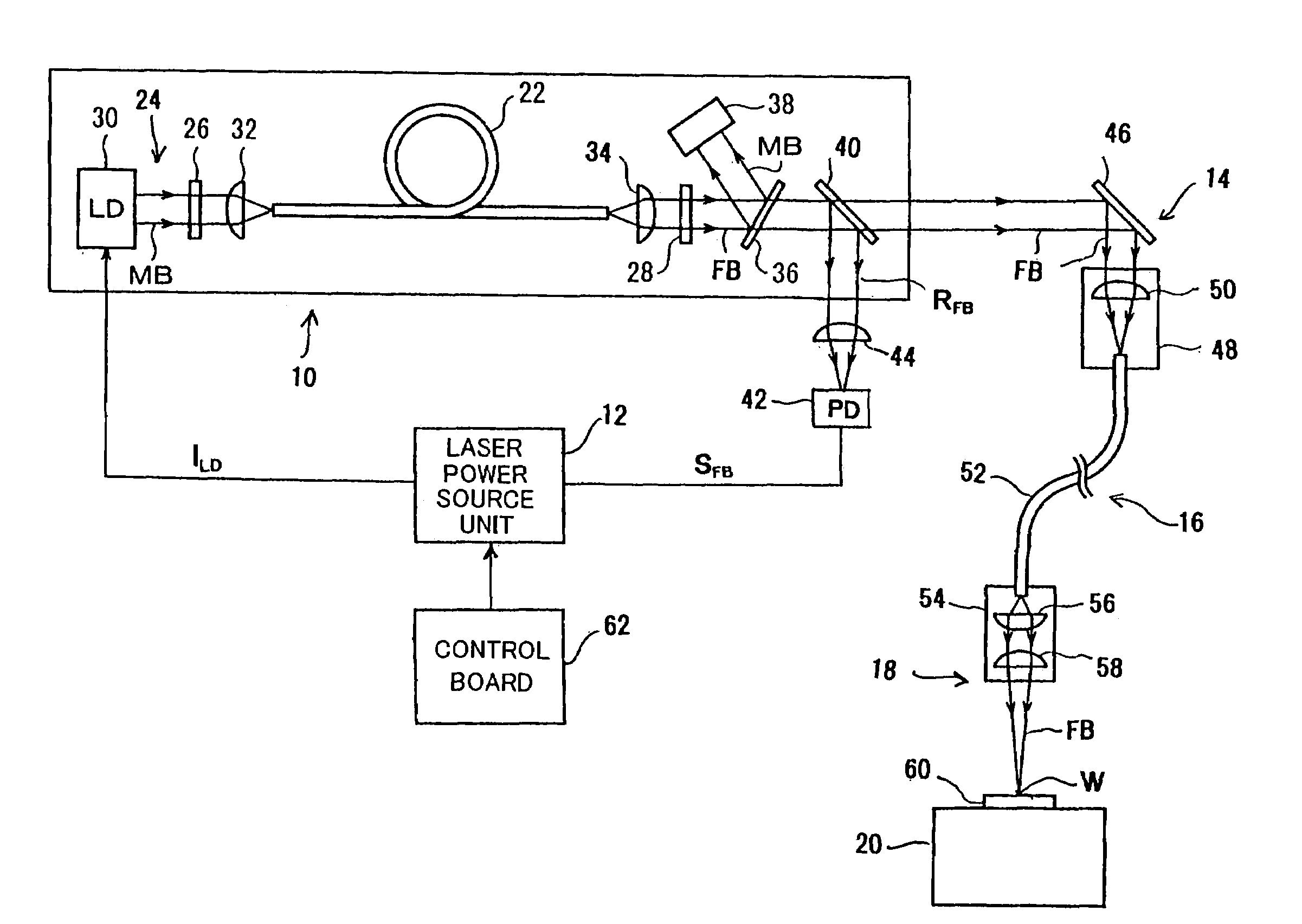
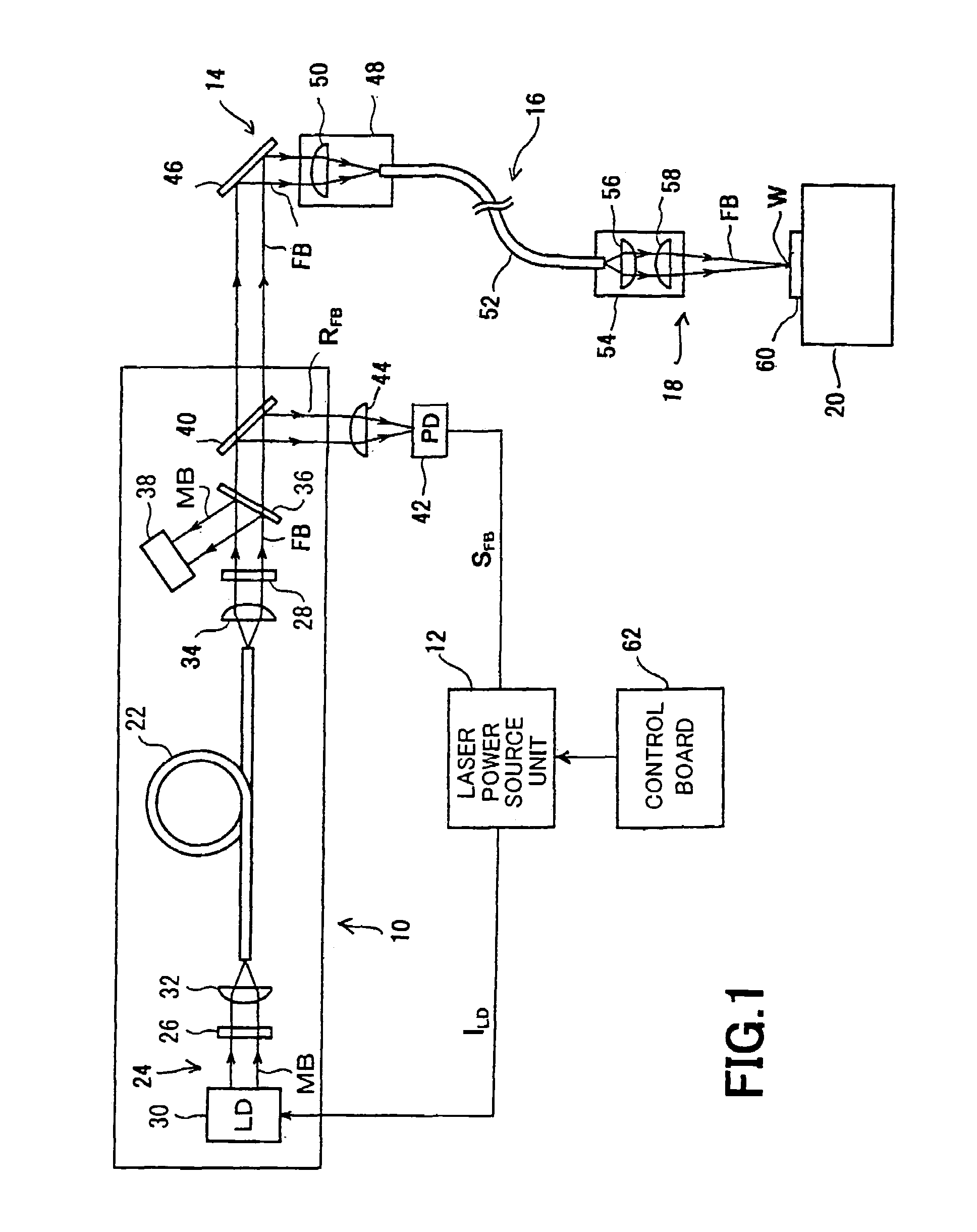
[0018]FIG. 1 depicts the configuration of a fiber laser beam processing apparatus according to an embodiment of the present invention. The fiber laser beam processing apparatus is configured to include a fiber laser oscillator 10, a laser power source unit 12, a laser beam injecting unit 14, a fiber transmission system 16, a laser beam irradiating unit 18, a processing table 20, etc.

[0019]The fiber laser oscillator 10 includes an optical fiber for oscillation (hereinafter, “oscillating fiber”) 22, an electric optical pumping unit 24 that applies an excitation beam MB for optical pumping onto an end face of the oscillating fiber 22, and a pair of optical resonator mirrors 26 and 28 optically facing each other through the oscillating fiber 22.

[0020]The electric optical pumping unit 24 includes a laser diode (LD) 30 and an optical lens 32 for condensing the b...


PUM

PropertyMeasurementUnit
diameteraaaaaaaaaa
wavelengthaaaaaaaaaa
currentaaaaaaaaaa

Abstract

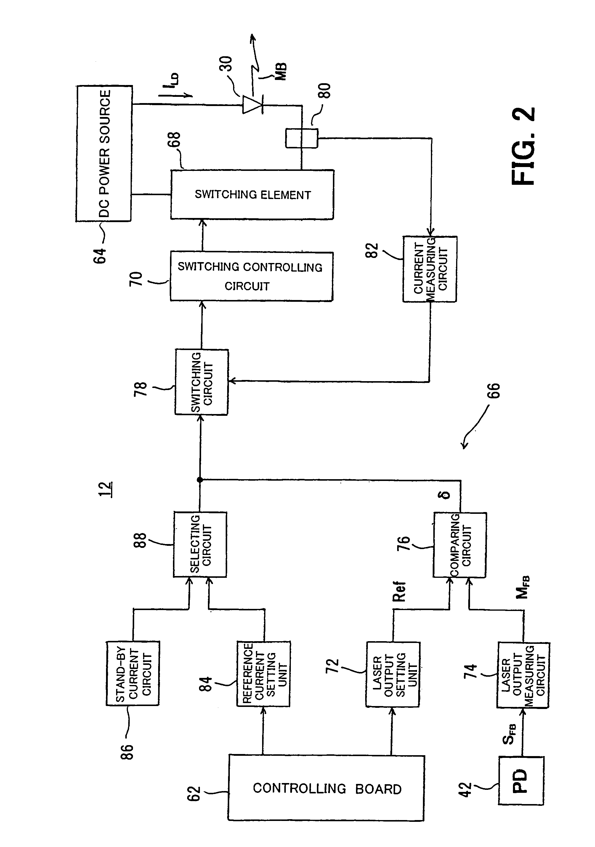
A fiber laser beam processing apparatus is configured by a fiber laser oscillator, a laser power source unit, a laser beam injecting unit, a fiber transmission system, a laser beam irradiating unit, a processing table, etc. A portion of a fiber laser beam oscillated and outputted by the fiber laser oscillator is received by a photo diode for monitoring the power through a beam splitter. An output signal of the photo diode is sent to a laser power source unit. The power source unit receives the output signal of the photo diode as a feedback signal and controls a driving current or an excitation current to be supplied to a laser diode of a pumping unit such that the laser output of the fiber laser beam equals a set value.

Description

BACKGROUND OF THE INVENTION[0001]1. Field of the Invention[0002]The present invention relates to a laser beam processing apparatus that executes laser beam processing using a fiber laser beam.[0003]2. Description of the Related Art[0004]Conventionally, a laser having an optical-fiber structure is known that oscillates and outputs a raw laser beam having a predetermined wavelength by optically pumping a core thereof including a luminous element using an excitation beam, so called a “fiber laser”. Because the fiber laser uses a very elongated core as the active medium thereof, the fiber laser can oscillate and output a laser beam having a small beam diameter and a small beam divergence angle (a fiber laser beam). In addition, the excitation beam injected into the fiber consumes completely the excitation energy thereof by crossing many times the core while the ray propagates on a long optical path and, therefore, a fiber laser beam can be created at a very high oscillation efficiency. ...

Claims


Application Information

Patent Timeline
Patent Type & Authority Patents(United States)
IPC IPC(8): H01S3/30B23K26/00
CPCH01S3/067H01S3/1312
Inventor MATSUDA, YASUSHISHIMADA, HIDENORIYAGINUMA, KOUICHITANAKA, SHINGO
Owner MIYACHI TECHNOS CORP
Learn More