Al technical title is built by PatSnap Al team. It summarizes the technical point description of the patent document.
a buffer and optical technology, applied in optics, instruments, electromagnetic transmission, etc., can solve problems such as the delay of idler signals relative to input signals
Inactive Publication Date: 2008-10-14
WSOU INVESTMENTS LLC +1
View PDF2 Cites 7 Cited by
Summary
Abstract
Description
Claims
Application Information
AI Technical Summary
This helps you quickly interpret patents by identifying the three key elements:
Problems solved by technology
Method used
Benefits of technology
Problems solved by technology
The idler signal is then applied to a dispersive medium, which propagates the idler signal at a different, e.g., slower, speed than the propagation speed of the input signal through the dispersive medium, thereby resulting in a delay of the idler signal relative to the input signal as it progresses through, and especially at the far end of the dispersive medium.
Method used
Image
Click on the blue label to locate the original text in one second.
Reading with bidirectional positioning of images and text.
Examples
Embodiment Construction
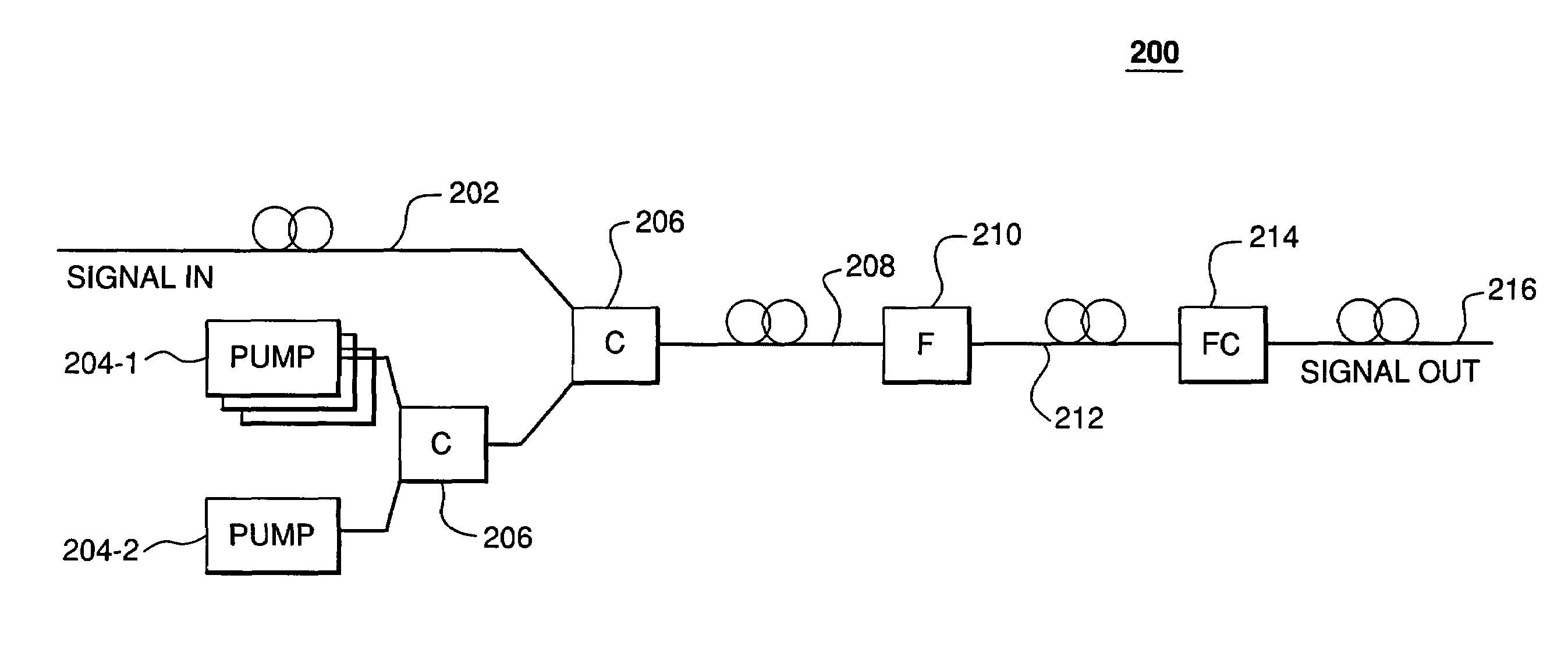
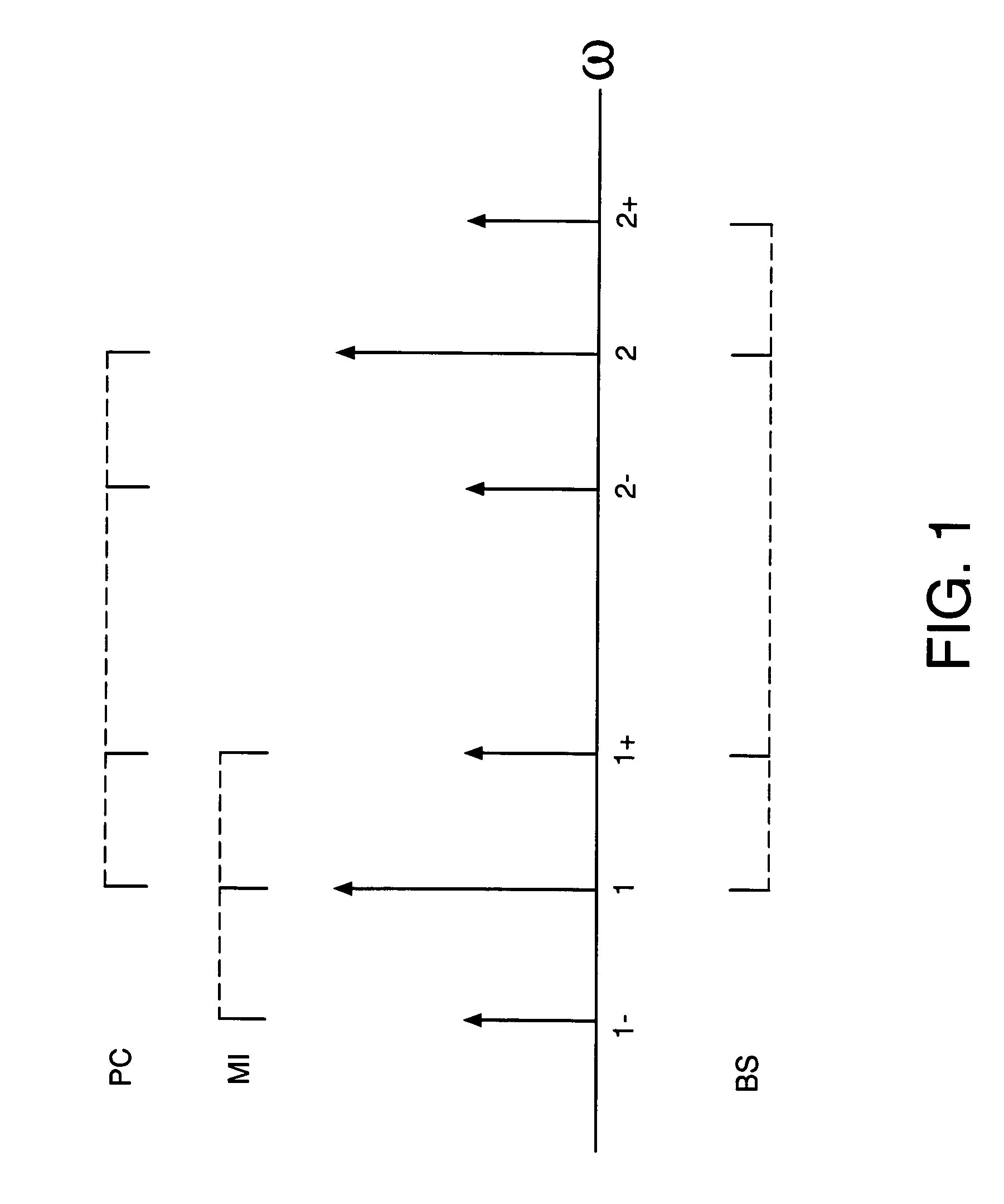
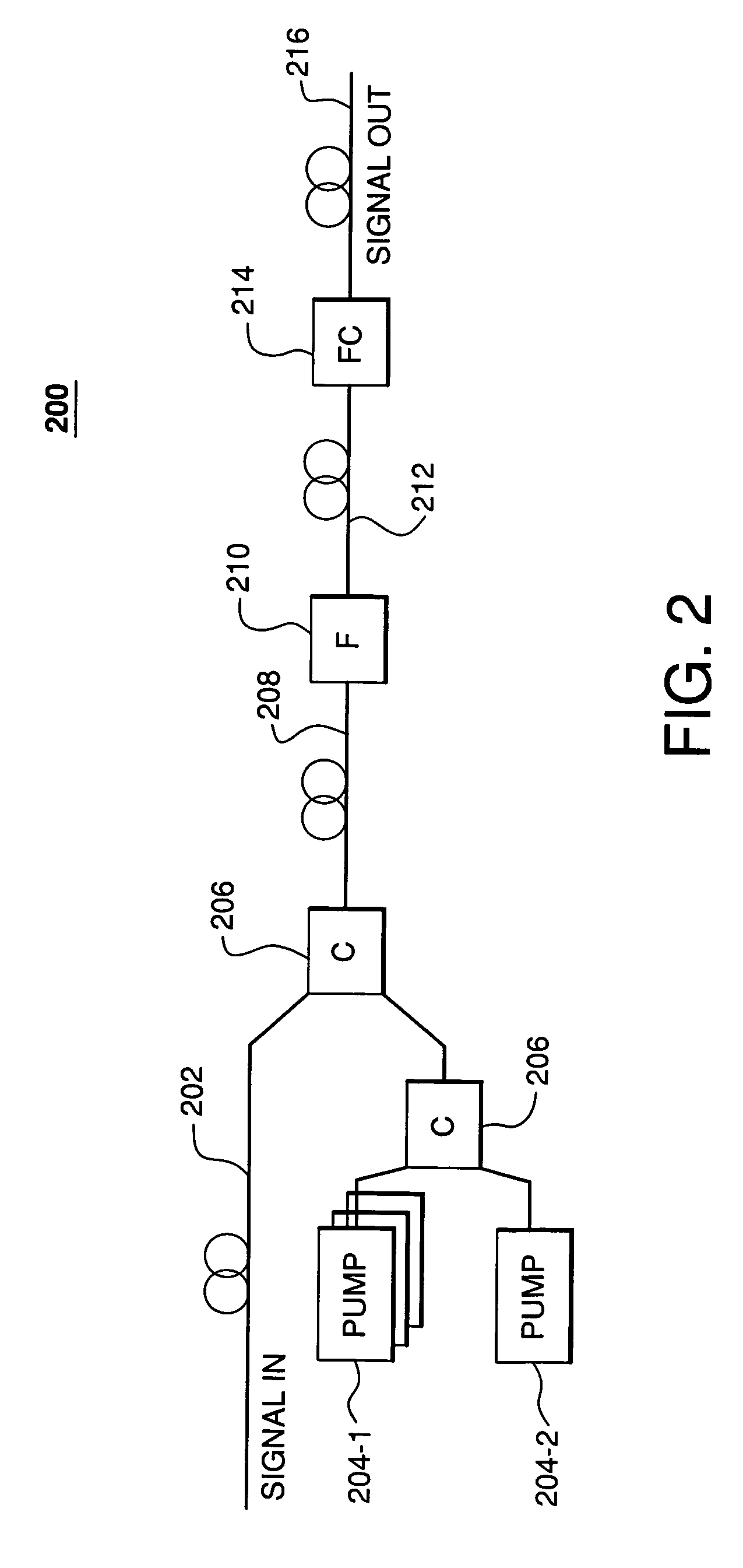
[0026]FIG. 2 shows a block diagram of an optical buffer 200, according to one embodiment of the present invention. Optical buffer 200 comprises two pumps 204-1 and 204-2, two couplers 206, four-wave-mixing (FWM) fiber 208, filter 210, dispersive fiber 212, and (optional) frequency converter 214. In the context of FIG. 1, couplers 206 combine pump waves ω1 and ω2 from pumps 204-1 and 204-2, respectively, with input signal ω1+ from input fiber 202 for transmission through FWM fiber 208. Note that the two two-way couplers 206 could be replaced by a single three-way coupler. FWM fiber 208 is any suitable fiber that supports Bragg scattering (BS), such as a suitable highly nonlinear fiber (HNF) or a photonic crystal fiber (PCF). To provide high-efficiency BS-based frequency conversion, FWM fiber 208 and the pump wave frequencies are selected such that ω0, the zero-dispersion frequency (ZDF) of the fiber, is approximately equal to (ω1++ω2) / 2.
[0027]Within FWM fiber 208, BS converts some (i...
PUM
Property
Measurement
Unit
length
aaaaa
aaaaa
optical
aaaaa
aaaaa
frequency
aaaaa
aaaaa
Abstract
An optical buffer employing Bragg scattering (BS), in which two pump signals are combined with an input (data) signal in a four-wave mixing (FWM) medium to frequency convert the input signal into an idler signal, which is applied to a dispersive medium, in which the idler signal propagates at a speed different from that of the input signal. By selectively turning on and off a pump, e.g., at bit-level switching rates, the BS-based frequency conversion can be selectively performed on particular bits in the input signal, e.g., to generate an output signal having reordered bits. A BS-based optical buffer can (1) be tuned to achieve different amounts of delay; (2) support single-channel or multiple-channel, classical or quantal communications; (3) be implemented with co-phased pump-phase modulation to suppress stimulated Brillouin scattering, while inhibiting spectral broadening of the idler signal; and (4) provide polarization independence using standard polarization-diversity techniques.
Description
BACKGROUND OF THE INVENTION[0001]1. Field of the Invention[0002]The invention relates to optical communications, and, in particular, to optical buffers employing four-wave mixing.[0003]2. Description of the Related Art[0004]All-optical communication systems have the potential to transmit information at bit rates higher than 10 Gb / s. Such systems employ tunable optical buffers, i.e., delay elements, with bit-level control, to implement bit-interleaved or packet-interleaved multiplexing, and to prevent conflicts among different bit streams at optical switches. M. Burzio, P. Cinato, R. Finotti, P. Gambini, M. Puleo, E. Vezzoni, and L. Zucchelli, “Optical cell synchronisation in an ATM optical switch,” Proc. ECOC 1994, pp. 581-584, the teachings of which are incorporated herein by reference, describe an optical buffer employing opto-electronic frequency conversion. J. E. Sharping, Y. Okawachi, J. van Howe, C. Xu, Y. Wang, A. E. Willner, and A. L. Gaeta, “All-optical, wavelength and band...
Claims
Application Information
Patent Timeline
Application Date:The date an application was filed.
Publication Date:The date a patent or application was officially published.
First Publication Date:The earliest publication date of a patent with the same application number.
Issue Date:Publication date of the patent grant document.
PCT Entry Date:The Entry date of PCT National Phase.
Estimated Expiry Date:The statutory expiry date of a patent right according to the Patent Law, and it is the longest term of protection that the patent right can achieve without the termination of the patent right due to other reasons(Term extension factor has been taken into account ).
Invalid Date:Actual expiry date is based on effective date or publication date of legal transaction data of invalid patent.