
FTTH PON that O/E converts 1310 nm for output to transmitters for E/O as 1550 nm

a technology transmitter, which is applied in the field of fiber to the home (ftth) system, can solve the problems of increasing the number of subscribers of a network, the wavelength band of 1310 nm may not be adaptable to and the difficulty of using the wavelength band of 1310 nm. achieve the effect of low cos

Inactive Publication Date: 2008-10-07
SAMSUNG ELECTRONICS CO LTD
View PDF7 Cites 12 Cited by
  • Summary
  • Abstract
  • Description
  • Claims
  • Application Information

AI Technical Summary

Benefits of technology

The present invention provides a PON-based FTTH system that can be used for a large number of subscribers and offers broadcasting services at a low cost. The system uses a wavelength band of 1550 nm and employs a direct modulation method for the optical transmitter, which allows for the simultaneous provision of satellite broadcasting services and other broadcasting services to subscribers. The technical effects of the invention include improved efficiency and cost-effectiveness for providing broadcasting services to large groups of subscribers.

Problems solved by technology

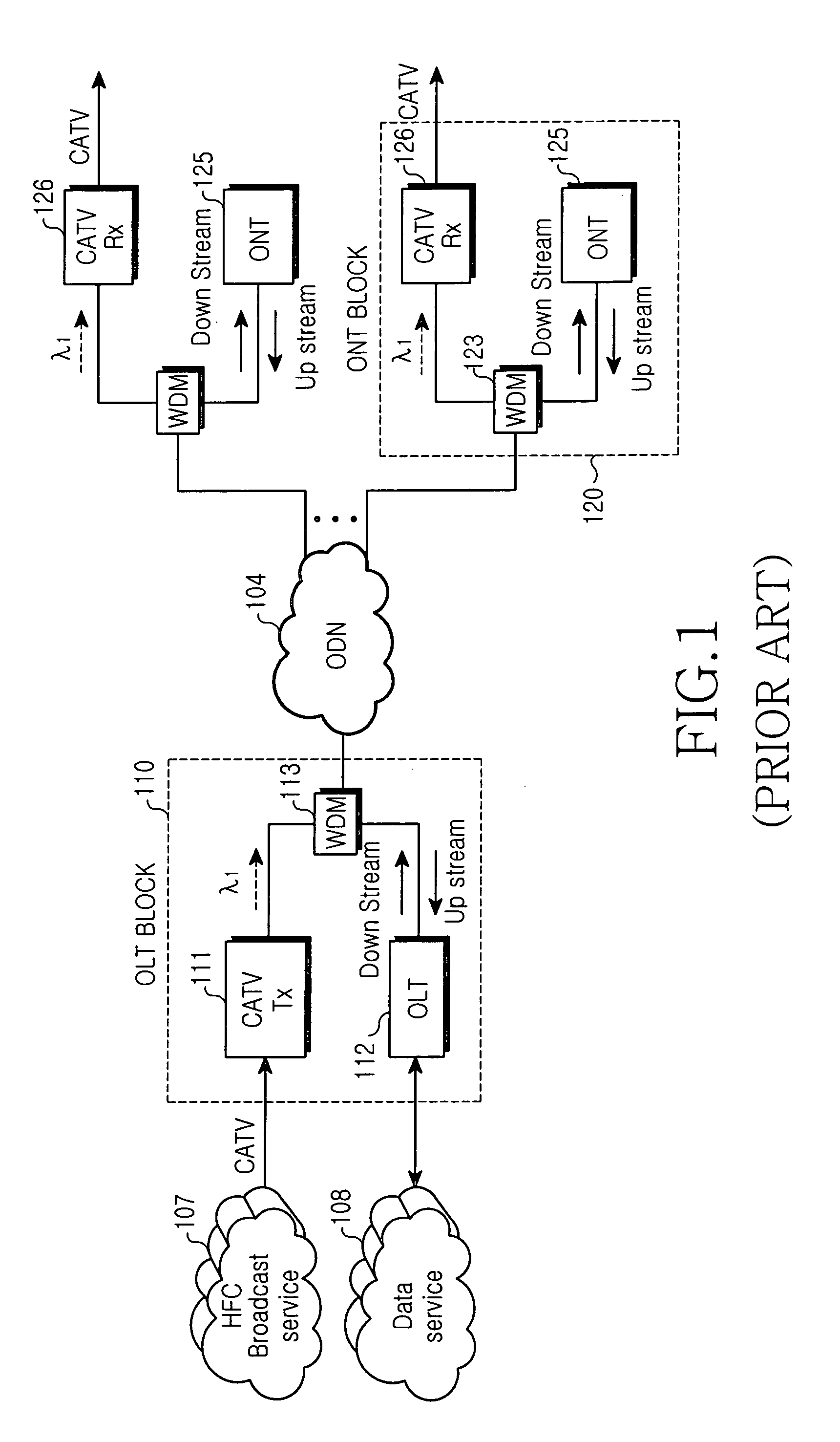
However, there is a great deal of difficulty in using the wavelength band of 1310 nm when constructing a network using an FTTH access network system.
In addition, optical fiber amplifiers that are currently in use may not be adaptable for the wavelength band of 1310 nm.
Accordingly, if the optical fiber amplifiers are not adaptable for 1310 nm, it becomes very difficult to increase the number of subscribers if a network is constructed by using a PON-based FTTH system.
However, the optical transmitter that employ the external modulation method require higher operational costs when compared with optical transmitters that employ a direct modulation method, so that costs for a broadcasting service may increase.
In other words, the currently used FTTH systems have no alternative / backup plan for subscribers' requirements for satellite broadcasting services.

Method used


Image

  • FTTH PON that O/E converts 1310 nm for output to transmitters for E/O as 1550 nm
  • FTTH PON that O/E converts 1310 nm for output to transmitters for E/O as 1550 nm
  • FTTH PON that O/E converts 1310 nm for output to transmitters for E/O as 1550 nm

Examples


Embodiment Construction

[0026]Hereinafter, several aspects of the present invention will be described in detail with reference to the accompanying drawings. Note that the same or similar components in drawings are designated by the same reference numerals as far as possible although they are shown in different drawings. For the purposes of clarity and simplicity, a detailed description of known functions and configurations incorporated herein will be omitted as it may obscure the subject matter of the present invention.

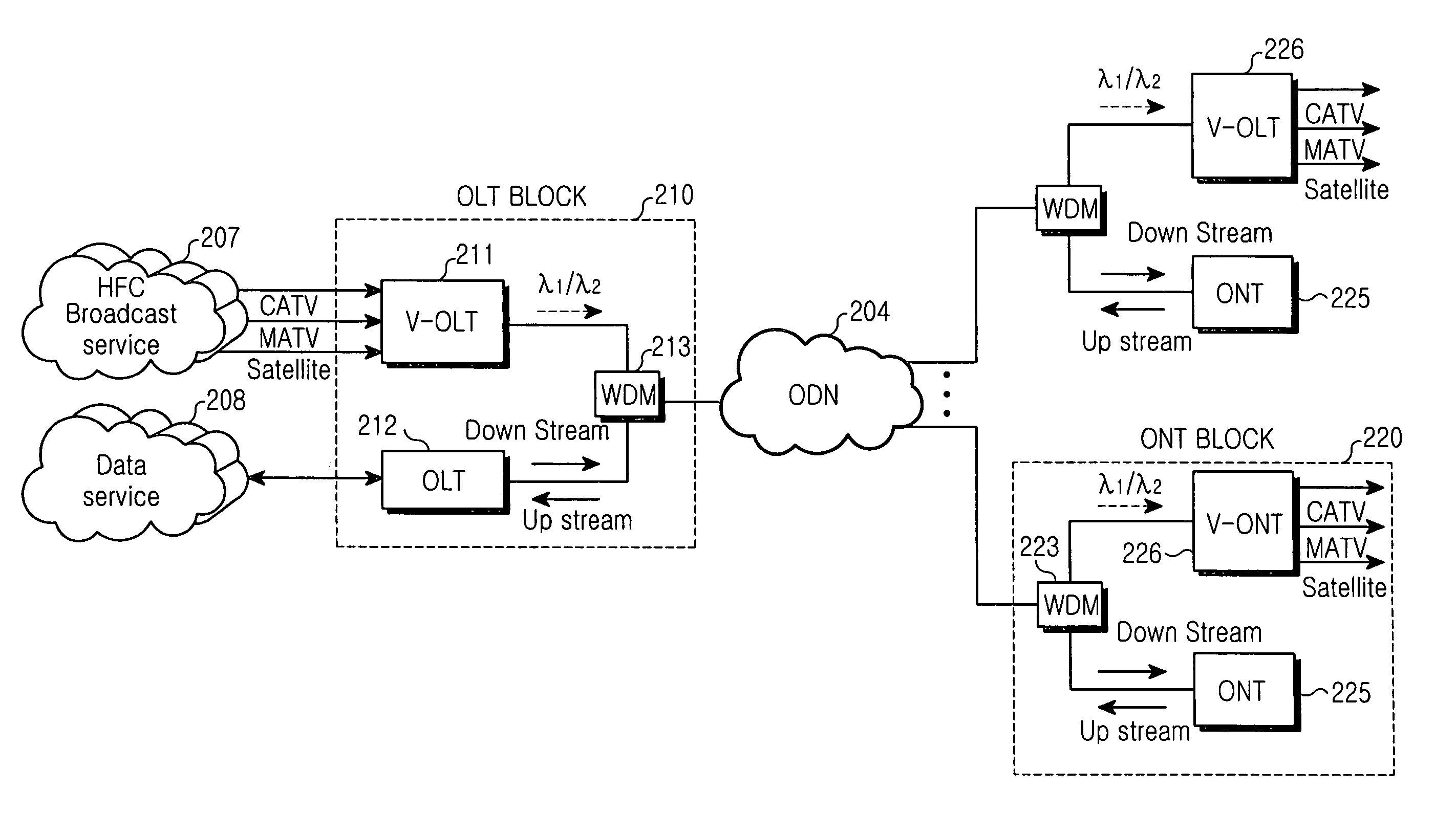
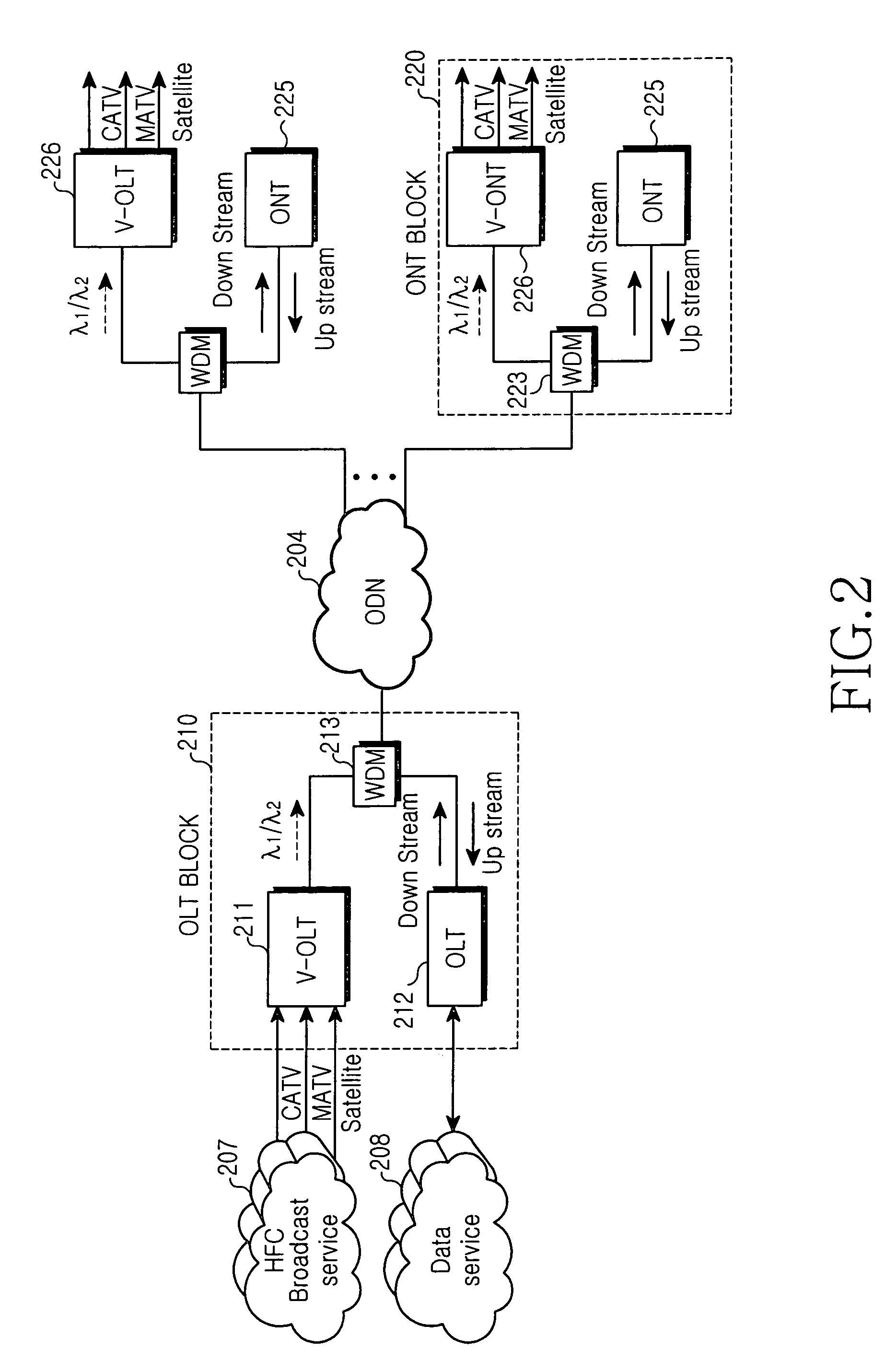
[0027]FIG. 2 is a schematic view showing an entire structure of a PON-based FTTH system according to a first aspect of the present invention. According to this aspect, the PON-based FTTH system includes a structure for providing master antenna TV (MATV), cable TV (CATV), and for satellite broadcasting. Referring to FIG. 2, the PON-based FTTH system includes an OLT block 210, an ONT block 220, and an ODN block 204. The OLT block 210 includes a video-optical line terminal (V-OLT) 211, an OLT 2...


PUM


Abstract

A fiber to the home (FTTH) system based on a passive optical network (PON) includes an optical line terminal (OLT) block, an optical network terminal (ONT) block, and an optical distribution network (ODN). The ONT block includes a video-optical line terminal (V-OLT) and an OLT to output optical signals of the V-OLT and the OLT by multiplexing the optical signals. The V-OLT receives cable TV (CATV), master antenna (MATV), and satellite broadcasting (SB) optical signals inputted from a broadcasting service network to output received signals as a first optical signal having a predetermined wavelength band. The ONT block includes a video-optical network terminal (V-ONT) and an (ONT) to split multiplexed data communications signals, and CATV broadcasting, MATV broadcasting, and (SB) optical signals. The V-ONT processes the split CATV broadcasting, MATV, and (SB) optical signals to provide subscribers with the split cable CATV, MATV and SB optical signals.

Description

CLAIM OF PRIORITY[0001]This application claims priority to an application entitled “FTTH system based on passive optical network for broadcasting service,” filed in the Korean Intellectual Property Office on Jan. 30, 2004 and assigned Ser. No. 2004-6144, the contents of which are hereby incorporated by reference.BACKGROUND OF THE INVENTION[0002]1. Field of the Invention[0003]The present invention relates to a Fiber To The Home (FTTH) system based on a passive optical network (PON) capable of providing subscribers with one or more of a high-speed data service, a voice service, and a broadcasting service using an optical fiber instead of an existing telephone line. More particularly, the present invention is related to a structure of a PON-based FTTH system and a method for establishing the same to provide a satellite broadcasting service by utilizing a conventional overlay CATV broadcasting service system in order to match the various / discriminated requirements of subscribers.[0004]2...

Claims


Application Information

Patent Timeline
Patent Type & Authority Patents(United States)
IPC IPC(8): H04N7/173H04B10/00H04J14/00H04N7/22H04J14/02
CPCH04J14/0226H04J14/0282H04N7/17309H04N21/6118H04N21/6168H04J14/0232H04J14/0234H04J14/0247H04J14/0252H04N7/10B65C1/02B65C9/02B65C9/1865B65C9/26B65C2009/407
Inventor PARK, SE-HONGKIM, SEONG-HAPARK, GIL-YONGPARK, TAE-SUNG
Owner SAMSUNG ELECTRONICS CO LTD
Learn More