
Methods, circuits, architectures, software and systems for determining a data transmission error and/or checking or confirming such error determinations

Inactive Publication Date: 2008-10-07
MARVELL ISRAEL MISL
View PDF51 Cites 34 Cited by
  • Summary
  • Abstract
  • Description
  • Claims
  • Application Information

AI Technical Summary

Benefits of technology

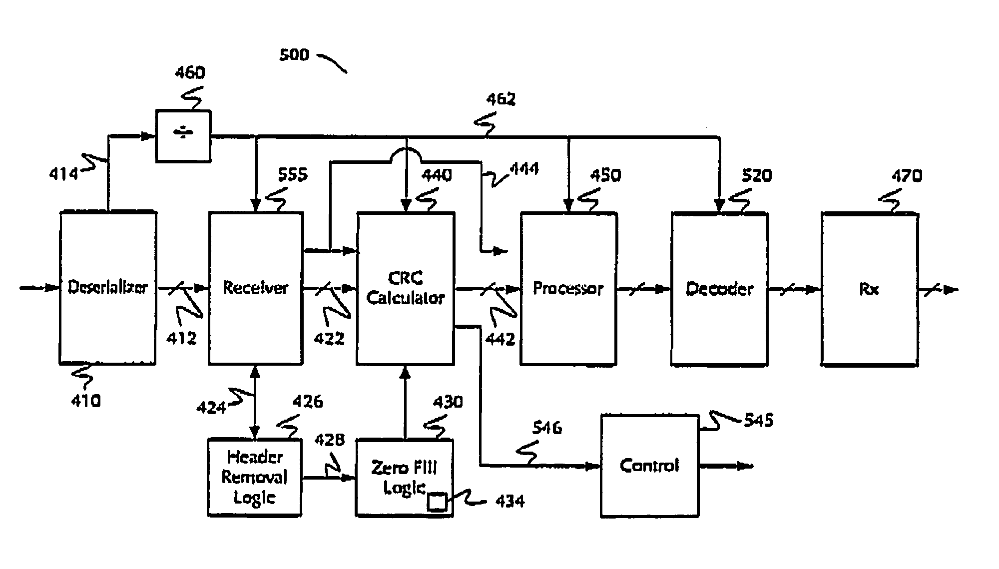
[0013]In the present invention, an error checking calculation is performed on error checking code transmitted with the data. If the transmitted data and error checking code are error-free, the error checking calculation gives a result having a known and / or predetermined state. This technique enables one to confirm or determine that the data transmission was error-free without use of or need for a wide and / or complicated comparator, thereby reducing the chip area dedicated to error detection, increasing the utilization efficiency of the circuitry on the chip, and reducing power consumption.

Problems solved by technology

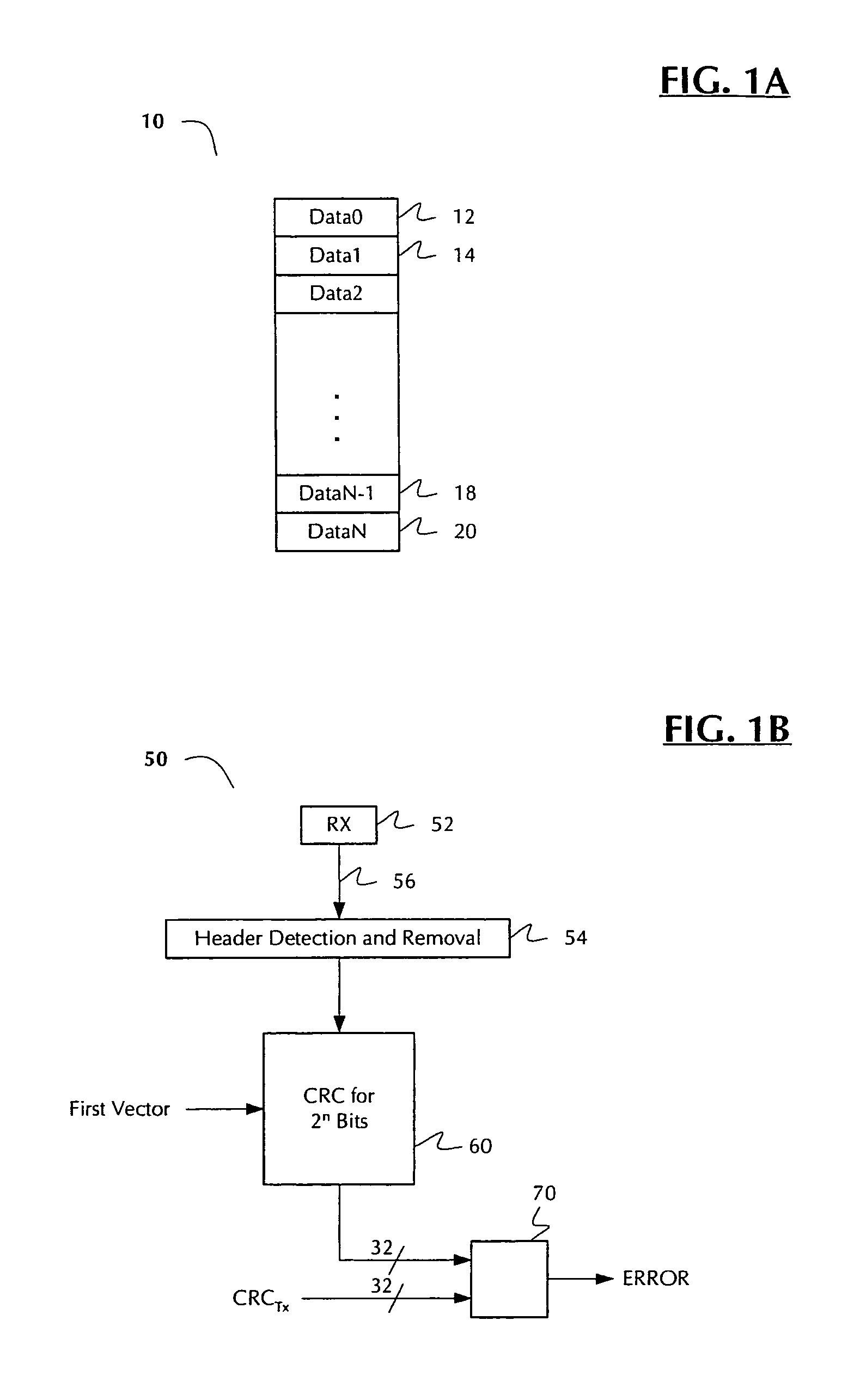
The approach becomes more complicated as data processing widths increase.
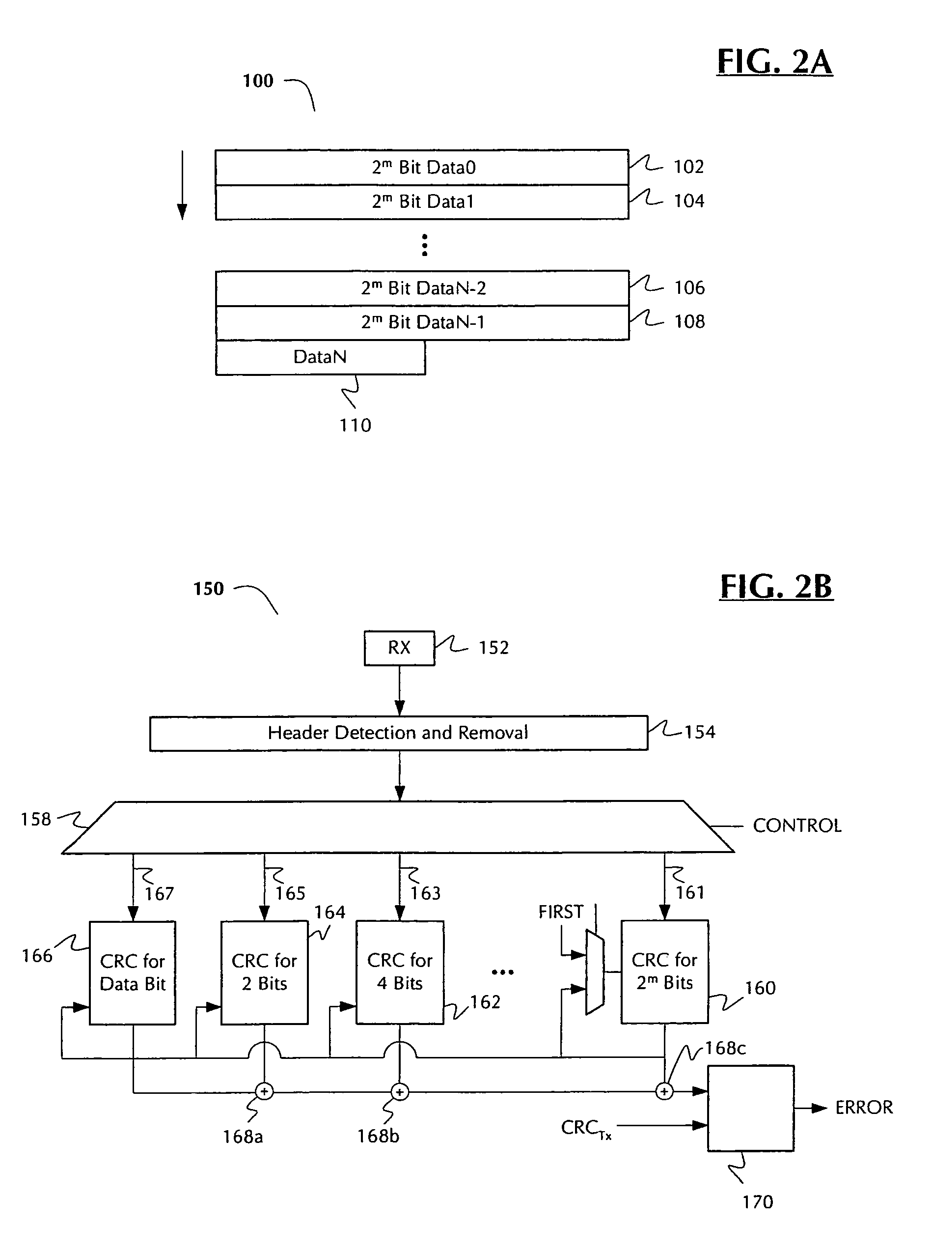
While providing some improvement over the approach of FIGS. 1A-1B in calculation time, the approaches of FIGS. 2A-2B in inefficient in terms of circuit use and / or chip area.
Such architectures also unnecessarily consume power to keep all of the CRC circuitry active, even when it is not in use.
In many cases, some bus lengths to and from second, third and / or fourth CRC blocks are relatively long, and thus consume incrementally greater power when transmitting data or even staying active, in comparison with the main (e.g., 2m bit) CRC block.

Method used


Image

  • Methods, circuits, architectures, software and systems for determining a data transmission error and/or checking or confirming such error determinations
  • Methods, circuits, architectures, software and systems for determining a data transmission error and/or checking or confirming such error determinations
  • Methods, circuits, architectures, software and systems for determining a data transmission error and/or checking or confirming such error determinations

Examples


Embodiment Construction

[0029]Reference will now be made in detail to the preferred embodiments of the invention, examples of which are illustrated in the accompanying drawings. While the invention will be described in conjunction with the preferred embodiments, it will be understood that they are not intended to limit the invention to these embodiments. On the contrary, the invention is intended to cover alternatives, modifications and equivalents, which may be included within the spirit and scope of the invention as defined by the appended claims. Furthermore, in the following detailed description of the present invention, numerous specific details are set forth in order to provide a thorough understanding of the present invention. However, it will be readily apparent to one skilled in the art that the present invention may be practiced without these specific details. In other instances, well-known methods, procedures, components, and circuits have not been described in detail so as not to unnecessarily ...


PUM


Abstract

Methods, circuits, architectures, and systems for error detection in transmitted data. The method generally includes the steps of (a) performing an error checking calculation on the transmitted data and appended error checking code; (b) determining the calculated error checking code state; and (c) if it has a predetermined state, indicating that there is no error in the transmitted data. The circuitry generally comprises (1) an error checking code calculation circuit configured to calculate error checking code on the transmitted data and the appended error checking code; (2) a vector selector configured to select one of a plurality of error checking vectors; and (3) a logic circuit configured to determine the calculated error checking code state and, if it has a predetermined state, indicate that there is no error in the transmitted data. The software generally includes a set of instructions configured to implement or carry out the present method. The architectures and / or systems generally include those that embody one or more of the inventive concepts disclosed herein. In the present invention, an error checking calculation is performed on error checking code transmitted with the data. If the transmitted data and error checking code are error-free, the error checking calculation gives a result having a known and / or predetermined state. This technique enables one to confirm or determine that the data transmission was error-free without use of or need for a wide, complicated comparator, thereby reducing the chip area dedicated to error detection, increasing the utilization efficiency of the circuitry on the chip, and reducing power consumption.

Description

RELATED APPLICATION(S)[0001]The present application may be related to the co-pending, commonly-owned applications entitled “Methods, Architectures, Circuits, Software and Systems for Transmission Error Determination” (Ser. No. 10 / 690,780, filed on Oct. 21, 2003; and / or “Method(s), Architecture(s), Circuits, Software and Systems for CRC Determinations” (Ser. No. 10 / 794,496, filed on Mar. 3, 2004; the disclosures of which are incorporated herein by reference in their entireties.FIELD OF THE INVENTION[0002]The present invention generally relates to the field of data transmission error determinations. More specifically, embodiments of the present invention pertain to methods, architectures, circuits, software and systems for determining a data transmission error and / or checking or confirming such an error determination.DISCUSSION OF THE BACKGROUND[0003]Cyclic redundancy checking (“CRC”) is a well-known, conventional technique for finding data transmission errors. Typically, CRC is perfo...

Claims


Application Information

Patent Timeline
IPC IPC(8): H03M13/09
CPCH03M13/091
Inventor BARASH, DROR
Owner MARVELL ISRAEL MISL
Learn More