
Synchronized UWB piconets for Simultaneously Operating Piconet performance

a technology of piconets and piconets, applied in the field of communication systems, can solve the problems of not being implemented, difficult to achieve, and large synchronization, and achieve the effect of synchronizing and operating piconets simultaneously

Active Publication Date: 2008-10-07
AVAGO TECH INT SALES PTE LTD
View PDF3 Cites 75 Cited by
  • Summary
  • Abstract
  • Description
  • Claims
  • Application Information

AI Technical Summary

Benefits of technology

The solution effectively reduces interference between simultaneously operating piconets, enabling reliable coexistence and high-data-rate communication without significant interference, even in close proximity, by synchronizing TDMA transmission slots and using TFCs to maintain orthogonality across piconets.

Problems solved by technology

However, other WPANs may be implemented such that the devices do not operate according to such an M / S (Master / Slave) type relationship.
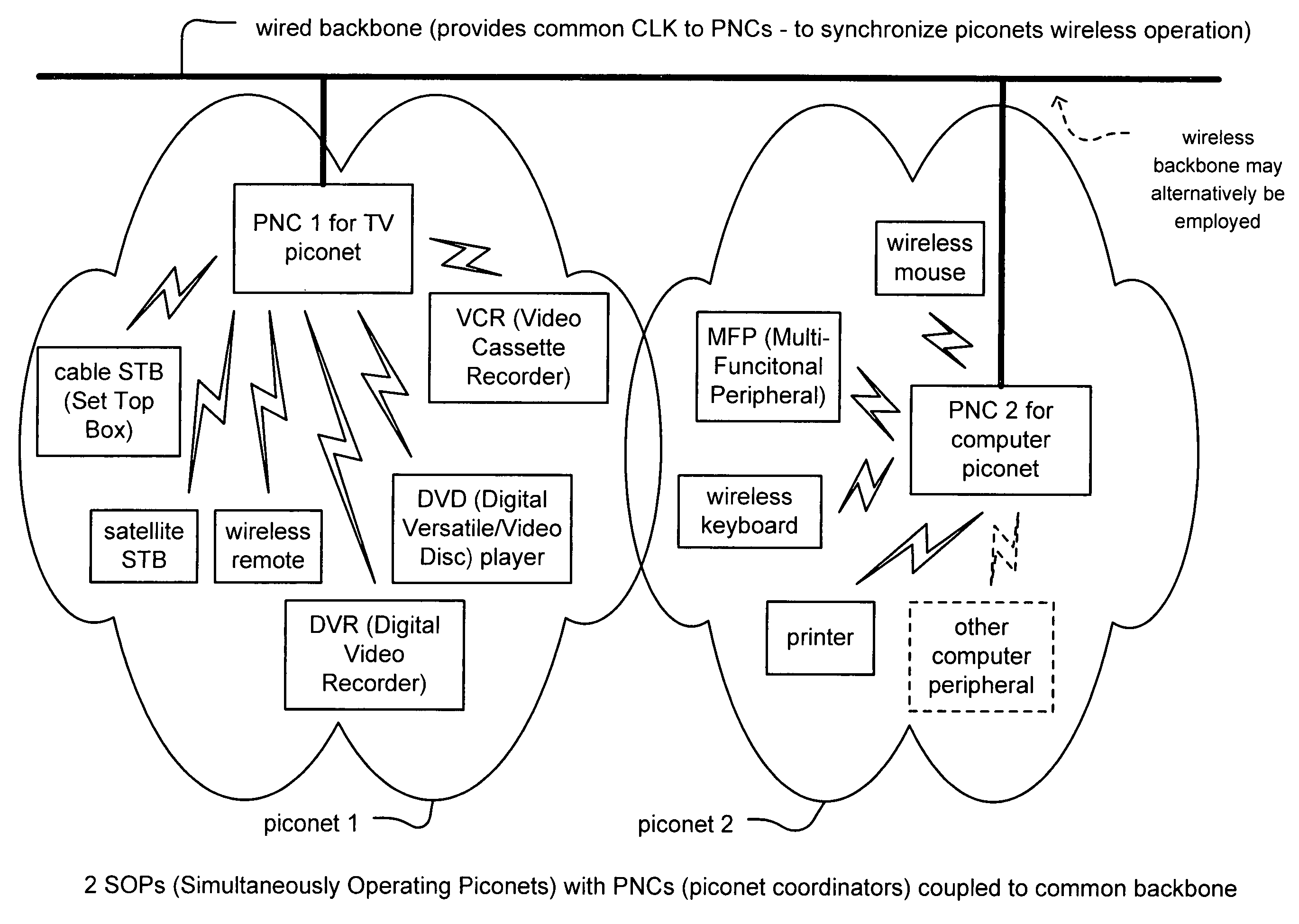
However, within a scatternet implementation, a problem may arise such that each of the individual piconets must be able to operate in relative close proximity with other piconets without interfering with one another.
This inherently requires a great deal of synchronization between the piconets, which may be very difficult to achieve in some instances.
It is also noted that independently operating piconets, not implemented within a scatternet implementation, may also suffer from deleterious effects of interference with other piconets located within relative close proximity.
One of the major concerns when operating a WPAN (that may include multiple SOPs relatively close to one another) is the undesirable interference that can occur between the devices of different piconets.
There are at present, insufficient means by which this undesirable interference may be minimized.

Method used


Image

  • Synchronized UWB piconets for Simultaneously Operating Piconet performance
  • Synchronized UWB piconets for Simultaneously Operating Piconet performance
  • Synchronized UWB piconets for Simultaneously Operating Piconet performance

Examples


Embodiment Construction

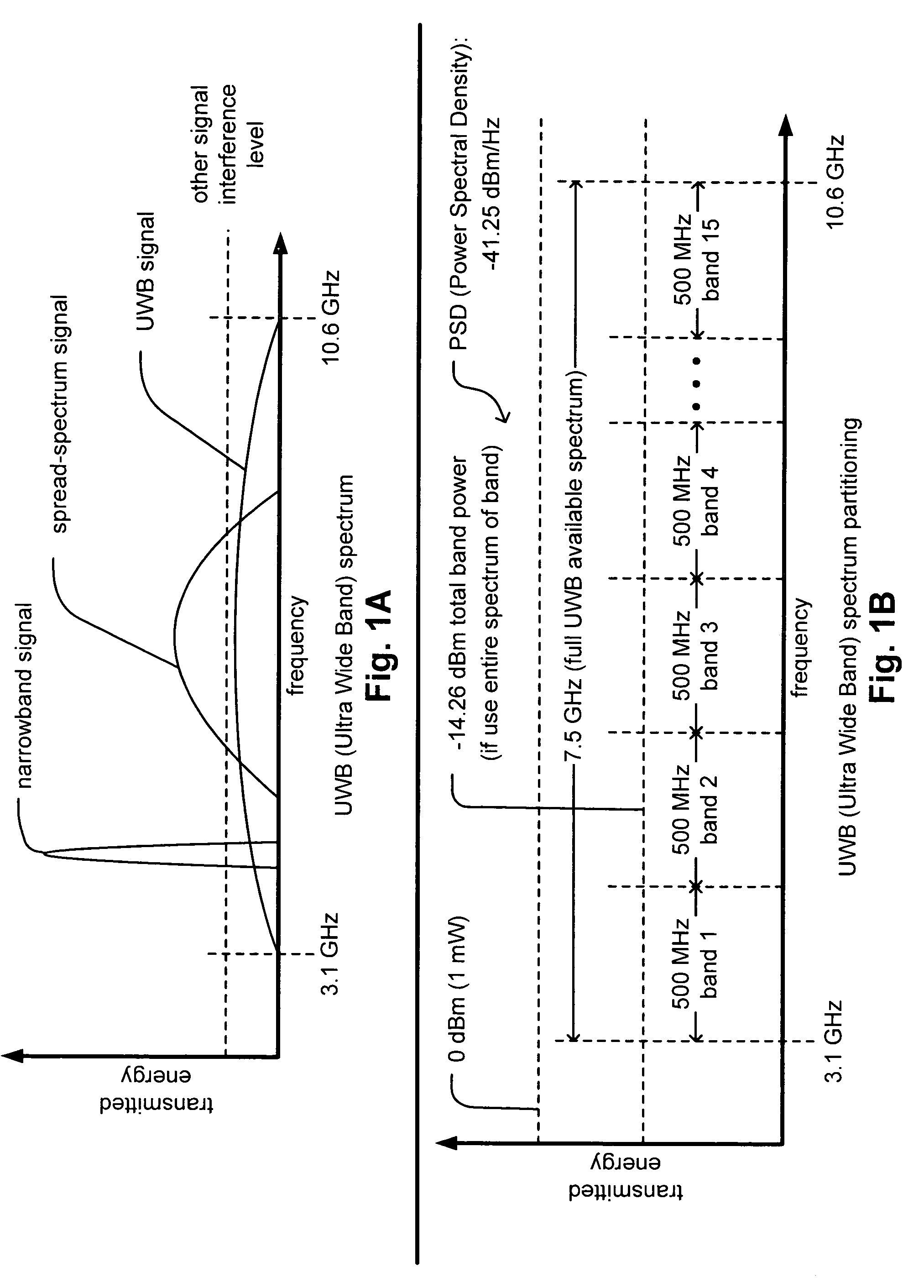
[0040]FIG. 1A is a diagram illustrating an embodiment of the frequency spectrum of a UWB (Ultra Wide Band) signal when compared to some other signal types according to the invention. UWB communications operate by sending pulses whose energy spreads across a broad frequency spectrum. For comparison, RF (Radio Frequency) communications typically operate by using a narrowband frequency carrier to transmit information. RF signals may be viewed as occupying a relatively narrowband range of frequency spectra. It is also noted that the PSD (Power Spectral Density) of a UWB signal typically does not rise above the PSDs of other interfering signals within an available spectrum of interest.

[0041]A UWB signal is one type of a spread-spectrum signal. A spread-spectrum signal may be viewed as a signal that occupies a frequency band that is much wider than the minimum bandwidth required by the information signal. For example, a transmitter “spreads” the energy (that is typically originally concen...


PUM


Abstract

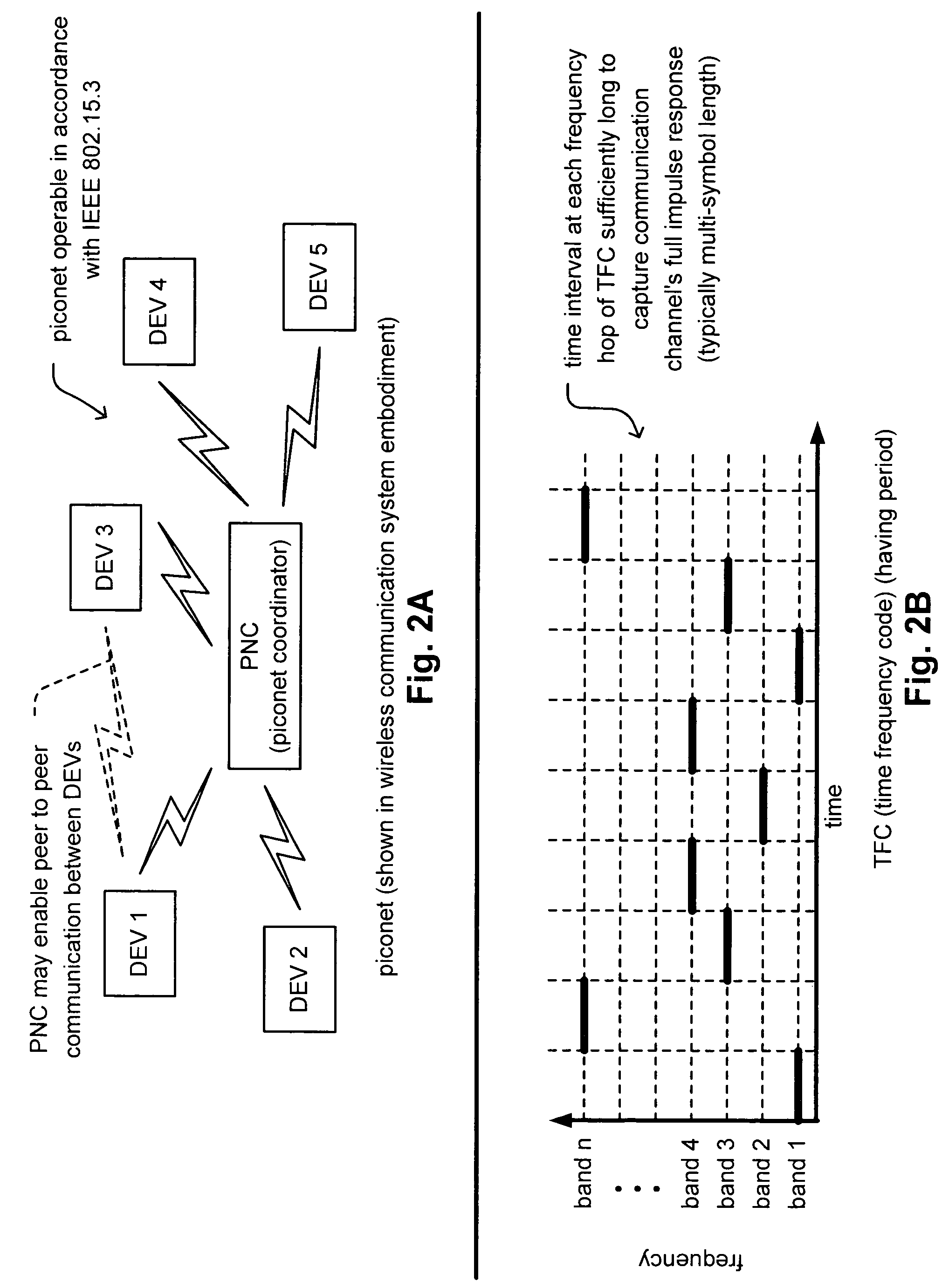
Synchronized UWB piconets for SOP (Simultaneously Operating Piconet) performance. A common backbone (either wired or wireless) is employed that provides a common CLK (clock signal) to all of the various PNCs (piconet coordinators) of various piconets that may operate within a sufficiently close region such that interference could undesirably occur. By providing a very reliable CLK signal from a common backbone to all of the PNCs of the various piconets operating within a substantially close proximity to one another, very precise synchronization may be ensured for all of the communications performed therein. The various piconets may then even operate using TDMA (Time Division Multiple Access)—whose performance would be substantially compromised without effective synchronization. In addition, combined TFC (time frequency code) and TDMA may also be employed to support the communications therein thereby providing even another degree of orthogonality that provided by TDMA alone.

Description

CROSS REFERENCE TO RELATED PATENTS / PATENT APPLICATIONS[0001]The present U.S. Utility patent application claims priority pursuant to 35 U.S.C. § 119(e) to the following U.S. Provisional Patent Application which is hereby incorporated herein by reference in its entirety and made part of the present U.S. Utility patent application for all purposes:[0002]1. U.S. Provisional Application Ser. No. 60 / 514,184, entitled “Synchronized UWB piconets for SOP (Simultaneously Operating Piconet) performance,” filed Oct. 24, 2003 (Oct. 24, 2003), pending.BACKGROUND OF THE INVENTION[0003]1. Technical Field of the Invention[0004]The invention relates generally to communication systems; and, more particularly, it relates to synchronization of communication between various devices within such communication systems.[0005]2. Description of Related Art[0006]Data communication systems have been under continual development for many years. In recent years, WPANs (Wireless Personal Area Networks) have been und...

Claims


Application Information

Patent Timeline
Patent Type & Authority Patents(United States)
IPC IPC(8): H04Q7/20H04B15/00H04Q7/00H04B1/69H04B7/00H04J3/06H04L7/00H04L12/28H04L12/56H04W16/14H04W56/00H04W84/18H04W92/02
CPCH04B1/7163H04B1/7183H04J3/0652H04W56/0015H04L7/0008H04W92/045H04W84/18H04W92/02H04W16/14
Inventor KARAOGUZ, JEYHANOJARD, ERIC J.FRANK, EDWARD H.
Owner AVAGO TECH INT SALES PTE LTD
Learn More