
Method for accurate high-resolution measurements of aspheric surfaces

a measurement method and high-resolution technology, applied in the direction of optical apparatus testing, optical radiation measurement, instruments, etc., can solve the problems of ineffective pure random average, inapplicability of spherical null test configuration to aspheric non-null test, etc., to improve the measurement accuracy of a metrology system and reduce the effect of uncalibrated errors

Active Publication Date: 2008-10-07
QED TECH INT
View PDF6 Cites 20 Cited by
  • Summary
  • Abstract
  • Description
  • Claims
  • Application Information

AI Technical Summary

Benefits of technology

[0018]Briefly described, the present invention provides methods for improving the measurement accuracy of a metrology system comprising a machine including multi-axis part-positioning means and an embedded wavefront-measuring gauge. These methods include steps for calibrating the focusing characteristics of an unknown optical system; setting the focus automatically with knowledge of only the test part's nominal local radius of curvature; calibrating the reference wave bias for aspheric wavefronts; and reduction of the effect of uncalibrated errors. These accuracy-improving methods are primarily applicable to higher spatial frequencies (more than a few undulations across the test part) on aspheric surfaces.
[0019]One aspect of the present invention is the calibration of the wavefront-measuring gauge's focusing characteristics. A priori knowledge of the imaging system is not required. The results of this one-time calibration, coupled with knowledge of the test part's nominal local radius of curvature in the measurement area, enable automatic focusing.
[0021]A third aspect of the present invention is another variation of the random-average technique that averages over wavefront slope in addition to space. There is a wavefront error component that depends on the slope of the measured wavefront (which is why a pure random average is ineffective for aspheric tests). Measuring the same location of a test part, but with different slope distributions (achieved, for example, by slightly tilting the test part), allows such slope-dependent errors to be reduced with averaging along with the usual spatially dependent reference wave biases.
[0022]A fourth aspect of the present invention suppresses the effects of low-spatial-frequency errors in the mid-spatial frequency band of a stitched measurement. When stitching, any low-spatial frequency errors will tend to induce stitching artifacts (e.g. steps at the subaperture edges) in the stitched result. Such edges have significant higher spatial frequency components, and thus low-frequency errors can corrupt the characterization of higher spatial frequencies. Eliminating the low spatial frequency components prior to stitching (by fitting or filtering them out) or actually optimizing them as compensators in the stitching can reduce the higher frequency corruption.
[0023]Applying various aspects of the present invention, either together or in part, provides improved measurement accuracy, particularly for measurements of higher spatial frequency structure on aspheres, as compared to the prior art.

Problems solved by technology

Since the systematic wavefront error varies with the profile measured, a calibration performed in a spherical null test configuration will not be applicable to an aspheric non-null test.
There is a wavefront error component that depends on the slope of the measured wavefront (which is why a pure random average is ineffective for aspheric tests).

Method used


Image

  • Method for accurate high-resolution measurements of aspheric surfaces
  • Method for accurate high-resolution measurements of aspheric surfaces
  • Method for accurate high-resolution measurements of aspheric surfaces

Examples


Embodiment Construction

[0045]The present invention provides methods for improving the measurement accuracy of a metrology system comprising a machine including multi-axis part-positioning means and an embedded wavefront-measuring gauge, e.g. a Fizeau interferometer. These methods reduce the error contributions of systematic errors in the gauge wavefront, particularly higher spatial frequency errors (more than a few undulations across the test part) in aspheric wavefronts.

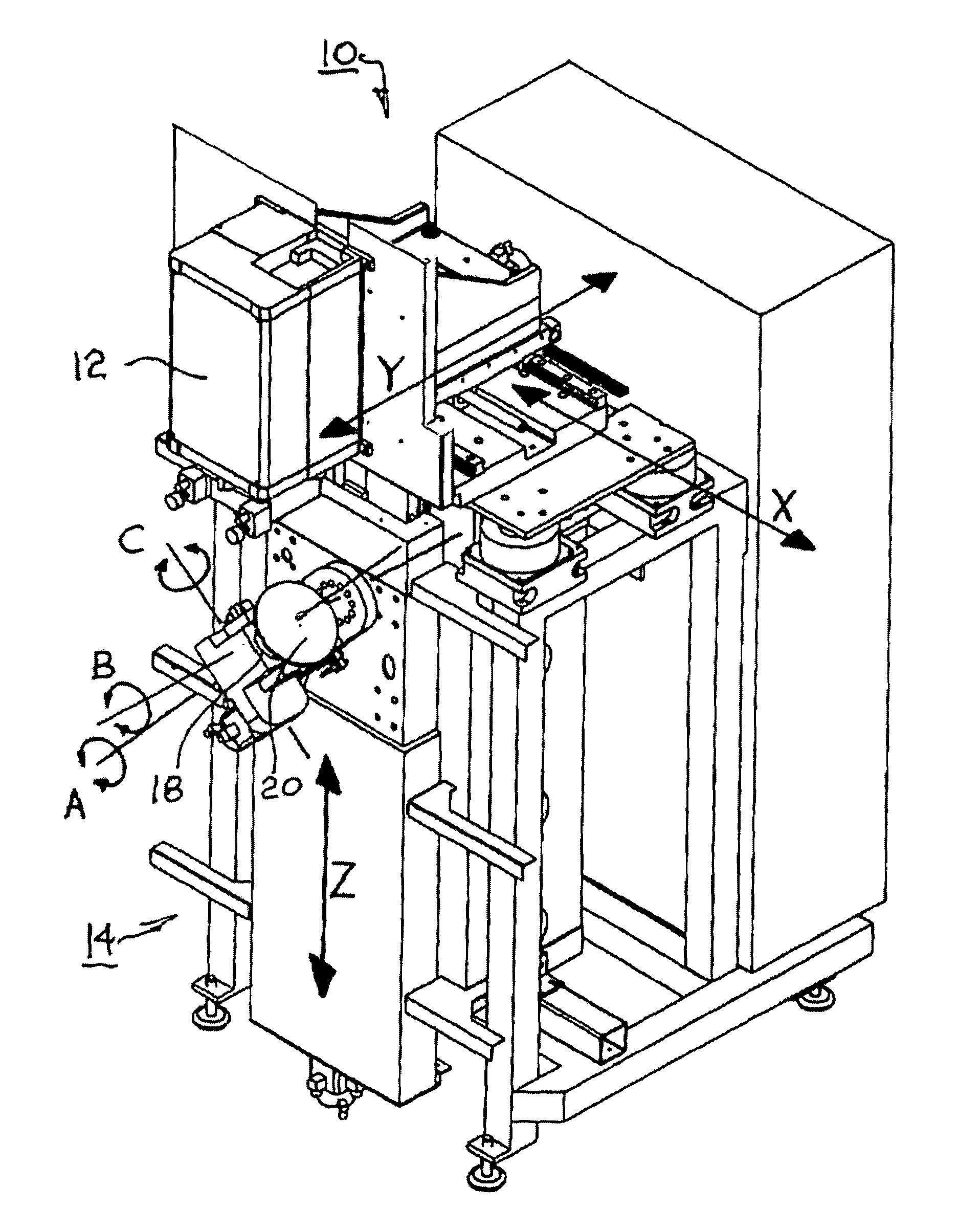
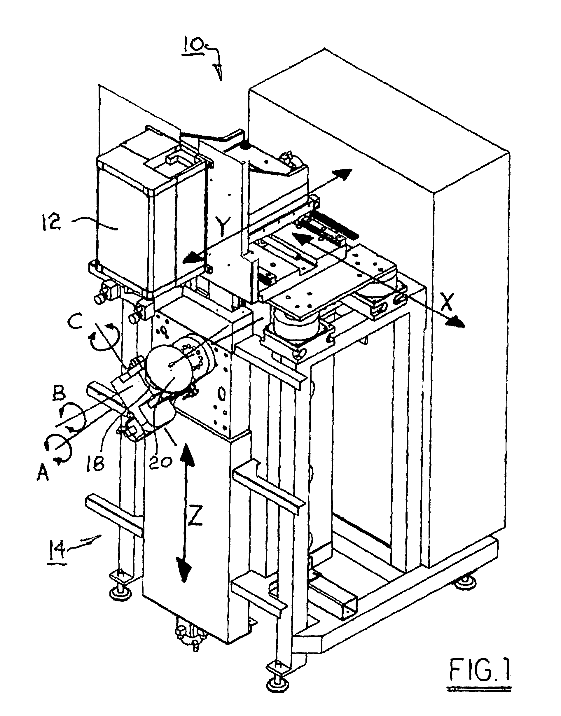
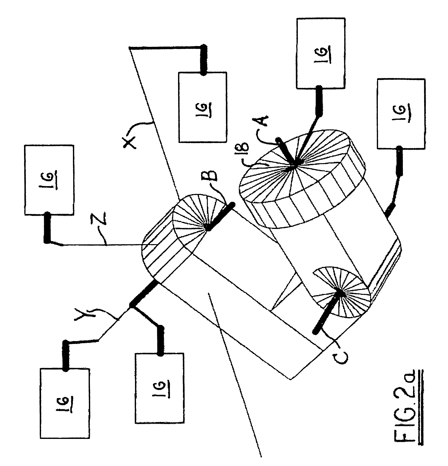
[0046]Referring to FIGS. 1 and 2, a metrology system 10 in accordance with the invention includes a wavefront gauge 12, for example, an interferometer, mounted to (“embedded” in) a multi-axis machine 14 defining a workstation having a stage 18 for receiving and moving a test part 20 during measurement thereof. A configuration of machine motions is shown (FIG. 2a) wherein there are six mechanical axes; three for translation (X, Y, Z) and three for rotation (A, B, C). It should be understood that other configurations of axes (including a di...


PUM


Abstract

A system comprising a plurality of methods for measuring surfaces or wavefronts from a test part with greatly improved accuracy, particularly the higher spatial frequencies on aspheres. These methods involve multiple measurements of a test part. One of the methods involves calibration and control of the focusing components of a metrology gauge in order to avoid loss of resolution and accuracy when the test part is repositioned with respect to the gauge. Other methods extend conventional averaging methods for suppressing the higher spatial-frequency structure in the gauge's inherent slope-dependent inhomogeneous bias. One of these methods involve averages that suppress the part's higher spatial-frequency structure so that the gauge's bias can be disambiguated; another method directly suppresses the gauge's bias within the measurements. All of the methods can be used in conjunction in a variety of configurations that are tailored to specific geometries and tasks.

Description

[0001]This application claims benefit of pending U.S. Provisional Application No. 60 / 668,385 filed Apr. 5, 2005.BACKGROUND OF THE INVENTION[0002]1. Field of the Invention[0003]The present invention relates to methods and apparatus for surface and wavefront measurements; more particularly to automated setup, calibration, and acquisition of such measurements; and most particularly, to such methods that improve the accuracy of aspheric surface and wavefront measurements.[0004]2. Discussion of the Related Art[0005]Methods and apparatus for making precision measurements of surfaces and optical wavefronts are well known in the prior art. The preferred devices for obtaining optical-quality measurements are (unsurprisingly) based on optical technology. The most widely accepted metrology instruments in this field are based on the principle of interferometry, though some other technologies are applicable.[0006]Such equipment has demonstrated capability to obtain measurements of exceptional ac...

Claims


Application Information

Patent Timeline
Patent Type & Authority Patents(United States)
IPC IPC(8): G01B11/24
CPCG01J9/02G01M11/025G01M11/0257G01M11/0271G01B9/02072G01B9/02039G01B9/02085G01B9/02057G01B9/02063G01M11/0278G01B11/00G01B11/14
Inventor MURPHY, PAUL E.MILADINOVIC, DRAGISHAFORBES, GREG W.DEVRIES, GARY M.FLEIG, JON F.
Owner QED TECH INT
Learn More