
Multi-band antenna

a multi-band antenna and antenna technology, applied in the direction of resonant antennas, antenna earthings, radiating elements structural forms, etc., can solve the problems of limiting the inner space of notebooks and going against the miniaturization development of portable electrical devices

Inactive Publication Date: 2008-09-30
HON HAI PRECISION IND CO LTD
View PDF5 Cites 10 Cited by
  • Summary
  • Abstract
  • Description
  • Claims
  • Application Information

AI Technical Summary

Benefits of technology

[0008]A primary object, therefore, of the present invention is to provide a multi-band antenna with compact structure and fitting to be installed in a notebook or other portable electrical devices.

Problems solved by technology

However, an antenna used in a notebook is limited by the inner space of the notebook.
Most conventional antennas having big structure go against miniaturization development of portable electrical device.
So, the PIFA antenna occupying big space in longitudinal direction goes against miniaturization development of portable electrical device.

Method used


Image

  • Multi-band antenna
  • Multi-band antenna
  • Multi-band antenna

Examples


Embodiment Construction

[0020]Reference will now be made in detail to a preferred embodiment of the present invention.

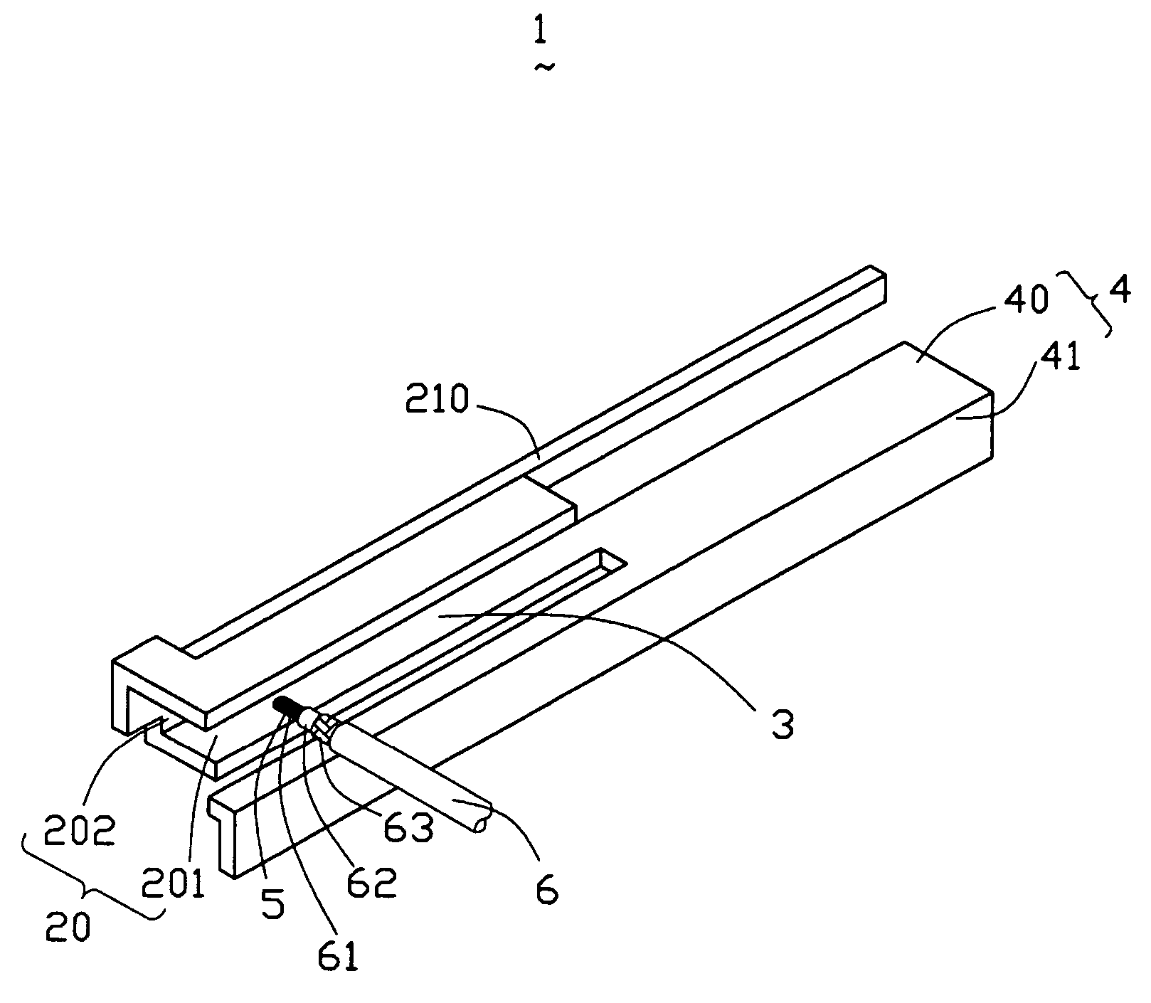
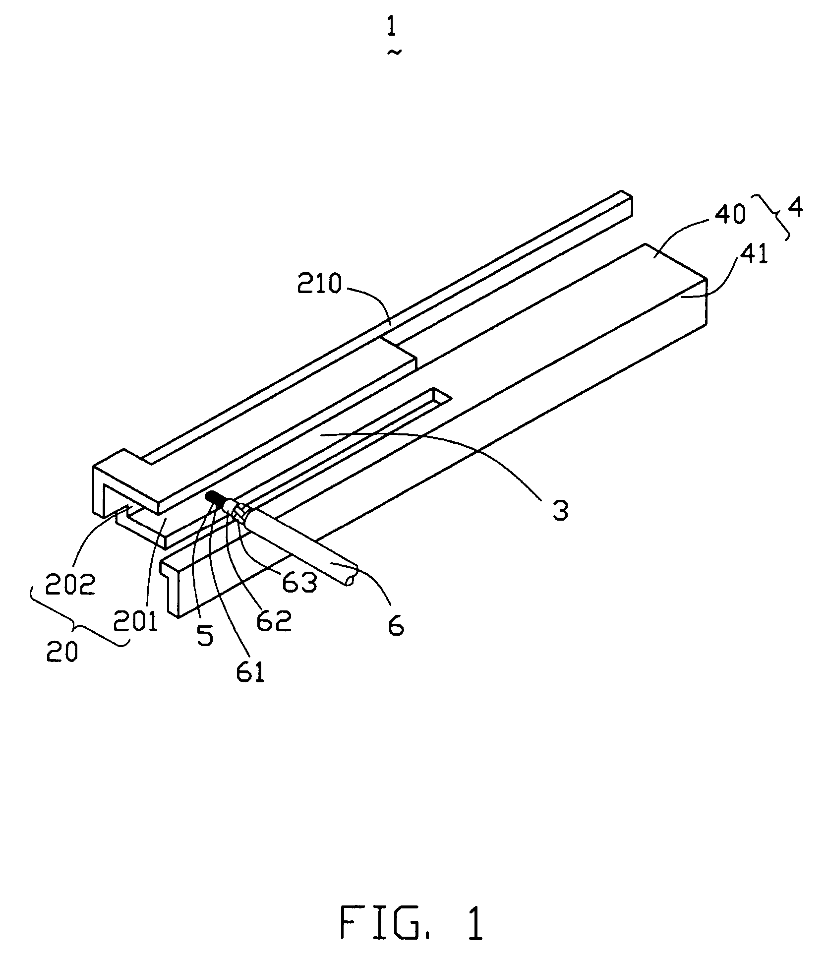
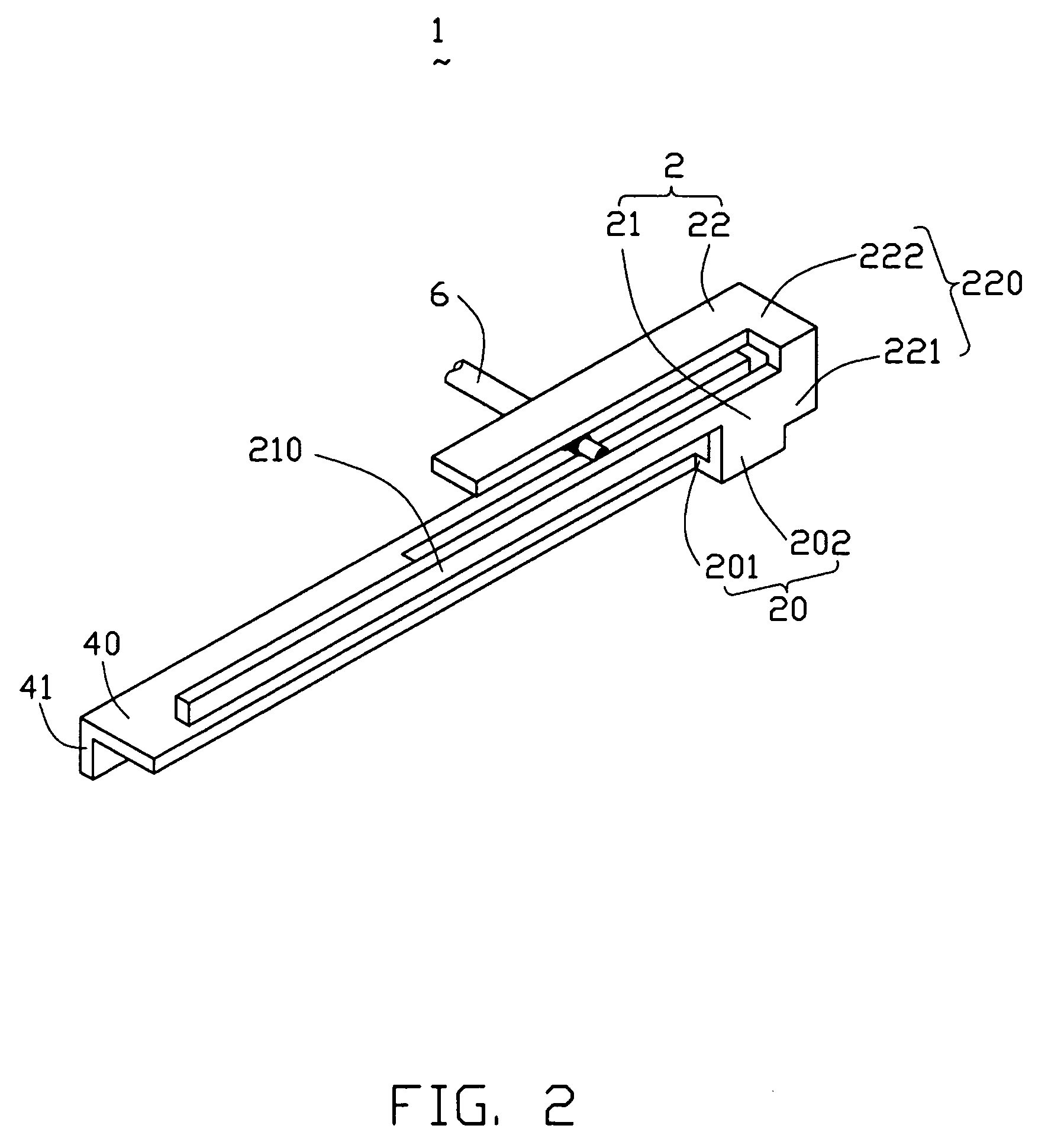
[0021]Referring to FIG. 1 to FIG. 4, a multi-band antenna 1 according to the present invention is made of a metal patch and shows a longitudinal structure along a longitudinal direction. The multi-band antenna 1 comprises a radiating element 2, a grounding element 4, a feeding line 6, and a connecting element 3 connecting the radiating element 2 and the grounding element 4.

[0022]The radiating element 2 comprises a first radiating section 21 operating at a lower frequency and a second radiating section 22 operating at a higher frequency. The first radiating section 21 and the second radiating section 22 extend along one common direction. The first radiating section 21 comprises a common radiating arm 20 and a first radiating arm 210 extending from the common radiating arm 20. The second radiating section 22 comprises the common radiating arm 20 and a second radiating arm 220 extending from t...


PUM


Abstract

A multi-band antenna used in an electronic device, comprising: a grounding element; a radiating element comprises a first radiating section operating at 900 MHz frequency band and a second radiating section operating at 1800 MHz frequency band; and a connecting section connecting the radiating element and the grounding element. The grounding element, the radiating element, and the connecting element locate respectively in the different plane. The whole structure of the multi-band antenna of the present invention designed combining the inner structure of the notebook or other portable electrical device. The multi-band antenna is suit to be installed in a notebook or other portable electrical device because the multi-band antenna occupies small space.

Description

BACKGROUND OF THE INVENTION[0001]1. Field of the Invention[0002]The present invention relates generally to an antenna, and more particularly to a multi-band antenna used in a portable electronic device.[0003]2. Description of the Prior Art[0004]With the development of wireless communication, more and more portable electronic devices, such as a notebook, install an antenna system for working in a Wireless Local-area Network (WLAN). Transmitting and receiving signals plays an important role in wireless communication process. In recent years, a majority of WLAN bases on Bluetooth technical standard or 802.11 technical standard. Antenna in Bluetooth technical standard is based on 2.4 GHz frequency band, and in 802.11 technical standard is based on 2.4 GHz and 5 GHz. So, antenna in notebook mostly works at the above frequency bands at the present time.[0005]However, an antenna used in a notebook is limited by the inner space of the notebook. So, the size of the antenna must be designed t...

Claims


Application Information

Patent Timeline
Patent Type & Authority Patents(United States)
IPC IPC(8): H01Q1/24
CPCH01Q1/22H01Q5/371H01Q1/2266
Inventor TAI, LUNG-SHENGKU, PO-KANGHUNG, CHEN-TAKE, YUN-LONGHUANG, YAO-SHIEN
Owner HON HAI PRECISION IND CO LTD
Learn More