Vehicular driving force distribution device

a technology of driving force and distribution device, which is applied in mechanical equipment, transportation and packaging, and gearing, etc., can solve the problems of decreased response and difficulty in engaging the paired clutches at the predetermined slip ratio with a high accuracy, and achieve the effect of simple construction and control

Inactive Publication Date: 2008-09-30
HONDA MOTOR CO LTD
View PDF6 Cites 8 Cited by
  • Summary
  • Abstract
  • Description
  • Claims
  • Application Information

AI Technical Summary

Benefits of technology

[0007]The present invention has been achieved in view of the above-mentioned circumstances, and has an object to provide a vehicular driving force distribution system for distributing torque between axles of right and left wheels, wherein differential limitation function is exerted by simple construction and control.
[0011]With the arrangement of the first feature, by engaging one or the other of right and left torque distribution clutches, one or the other of any two elements among three elements of the planetary gear mechanism is locked to the fixed portion, whereby torque can be distributed between the axles of right and left wheels. Also, if the differential limitation clutch is engaged to control the relative rotation of any two elements among three elements of the planetary gear mechanism, the planetary gear mechanism enters a locked state, so that the axles of the right and left wheels are integrated to perform differential limitation. By the arrangement of merely providing the differential limitation clutch, differential limitation can be performed by simple control and moreover the control response is improved, as compared with the case where differential limitation is performed by controlling the engagement forces of the right and left torque distribution clutches.
[0014]With the arrangement of the second feature, since the differential limitation clutch controls the relative rotation of the sun gear and the carrier member of the planetary gear mechanism, designing the layout of the differential limitation clutch becomes easy and the size of the vehicular driving force distribution system can be reduced, as compared with the case where the relative rotation of a ring gear and the sun gear or the relative rotation of the ring gear and the carrier member is controlled.

Problems solved by technology

However, it is difficult to engage the paired clutches at the predetermined slip ratio with a high accuracy, and the control thereof is complicated to raise a problem of decreased response.

Method used


Image

  • Vehicular driving force distribution device
  • Vehicular driving force distribution device
  • Vehicular driving force distribution device

Examples


second embodiment

[0064]Next, the present invention is described with reference to FIG. 8.

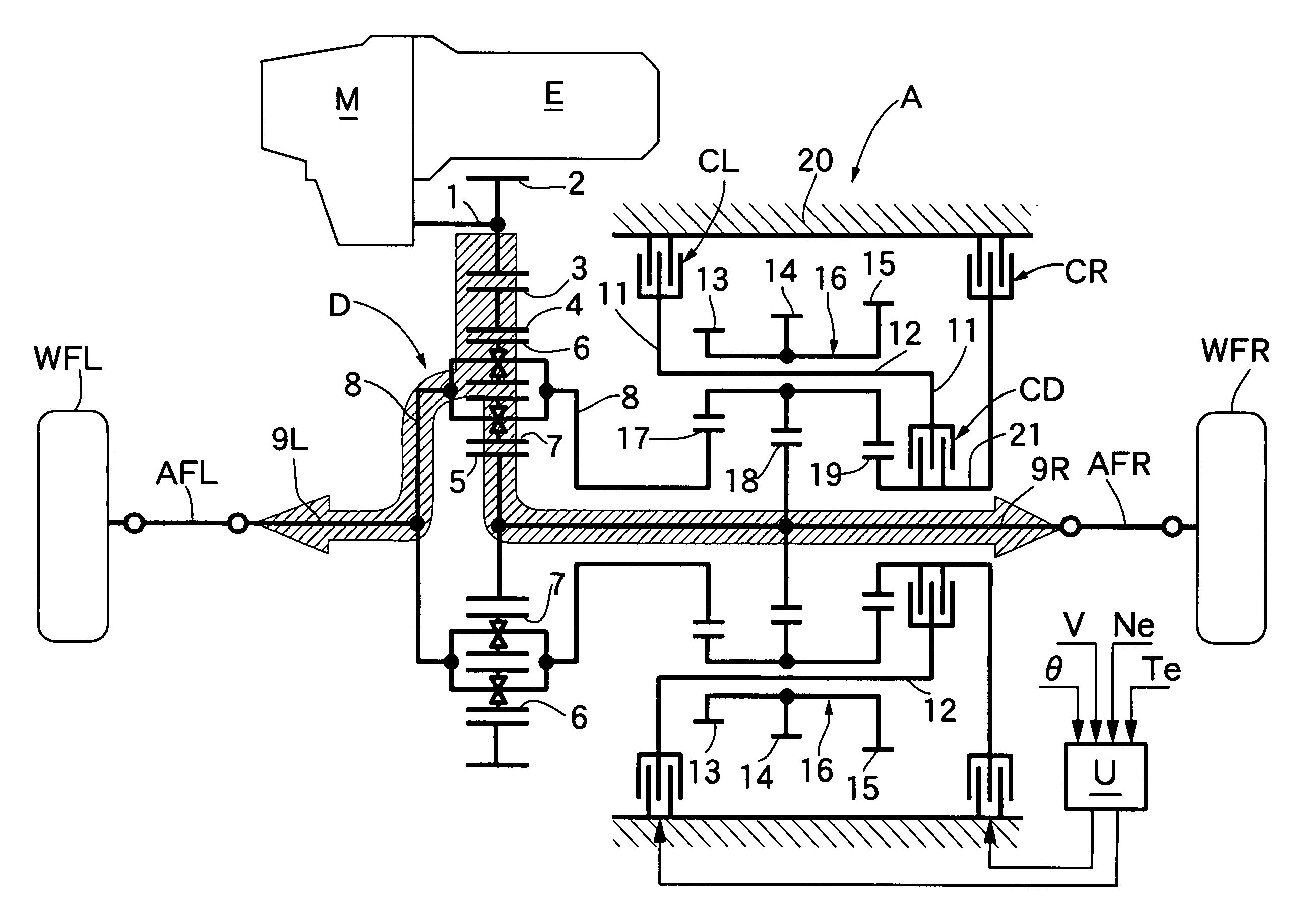
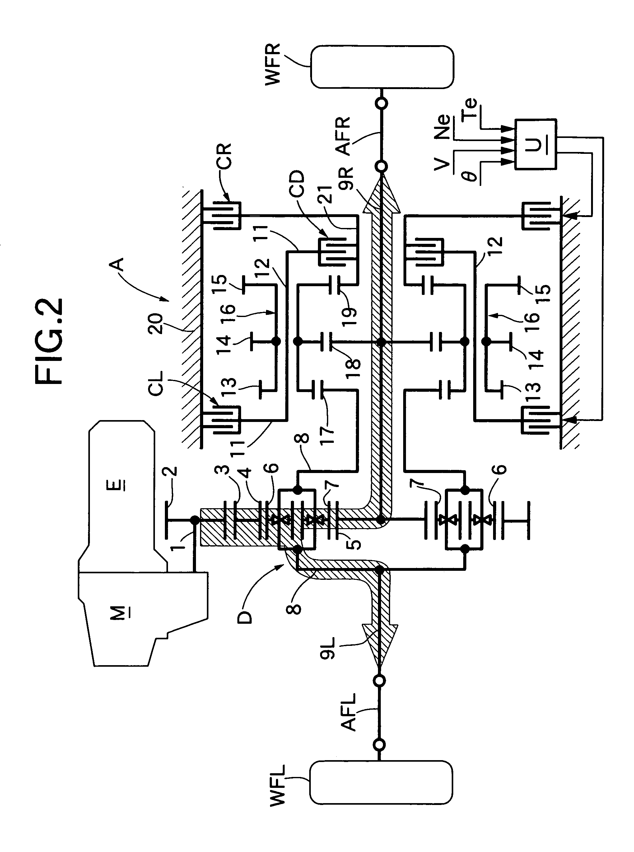
[0065]In the first embodiment shown in FIG. 2, the differential limitation clutch CD connects the third sun gear 19 to the carrier member 11. However, in the second embodiment shown in FIG. 8, the differential limitation clutch CD integrally connects a ring gear 22 meshing with the first pinion 13 and the carrier member 11 to each other to lock the planetary gear mechanism. Even if, instead of the ring gear 22 meshing with the first pinion 13, a ring gear meshing with the second pinion 14 or a ring gear meshing with the third pinion 15 is integrally connected to the carrier member 11, the same operation and effect can be achieved.

third embodiment

[0066]Next, the present invention is described with reference to FIG. 9.

[0067]In the first embodiment shown in FIG. 2, the differential limitation clutch CD connects the third sun gear 19 to the carrier member 11. However, in the third embodiment shown in FIG. 9, the differential limitation clutch CD integrally connects a ring gear 23 meshing with the third pinion 15 and the third sun gear 19 to each other to lock the planetary gear mechanism. Even if, instead of the ring gear 23 meshing with the third pinion 15, a ring gear meshing with the second pinion 14 or a ring gear meshing with the first pinion 13 is integrally connected to the third sun gear 19, the same operation and effect can be achieved.

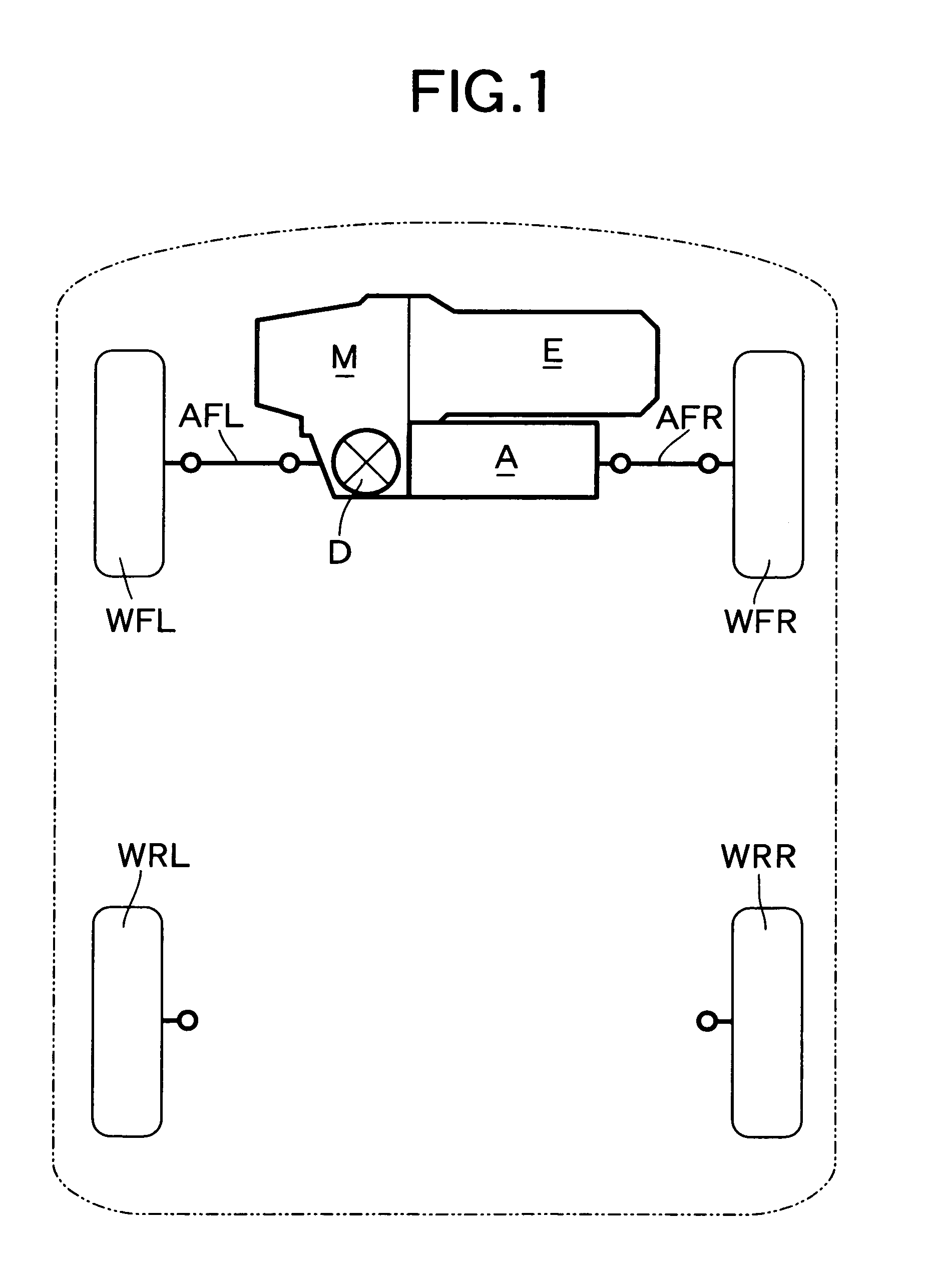
[0068]A fourth embodiment shown in FIG. 10 is a modification of the first embodiment. In the first embodiment, the torque distribution mechanism A is arranged on the front wheel WFL, WFR side of the front-engine front-drive vehicle. However, in the fourth embodiment, the differential gea...


PUM


Abstract

In a vehicular driving force distribution system, a left or right torque distribution clutch is selectively engaged to lock a carrier member or a sun gear of a planetary gear mechanism, whereby torque can be distributed between left and right wheels. Also, if a differential limitation clutch is engaged to control relative rotation of the sun gear and the carrier member of the planetary gear mechanism, the planetary gear mechanism enters a locked state, so that the left and right wheels are integrated to perform differential limitation. By the arrangement of merely providing the differential limitation clutch, the differential limitation can be performed by simple control and moreover the control response is improved, as compared with the case where differential limitation is performed by controlling engagement forces of the left and right torque distribution clutches.

Description

RELATED APPLICATION DATA[0001]The Japanese priority application Nos. 2005-200526 and 2006-135557 upon which the present application is based are hereby incorporated in their entirety herein by reference.BACKGROUND OF THE INVENTION[0002]1. Field of the Invention[0003]The present invention relates to a vehicular driving force distribution system comprising a torque distribution mechanism which includes a planetary gear mechanism and which is arranged between axles of left and right wheels, any two elements among three elements of the planetary gear mechanism being locked to a fixed portion via torque distribution clutches, respectively, so that torque is distributed between the axles of the left and right wheels.[0004]2. Description of the Related Art[0005]Such a vehicular driving force distribution system is disclosed in Japanese Patent Application Laid-open No. 8-114255. In this vehicular driving force distribution system, a torque transmission means comprising a planetary gear mech...

Claims


Application Information

Patent Timeline
Patent Type & Authority Patents(United States)
IPC IPC(8): F16H48/22F16H48/10F16H48/11F16H48/38
CPCB60K23/04F16H48/30F16H48/22F16H48/10
Inventor HONDA, KENJISHIBAHATA, YASUJIOHMURA, JUN
Owner HONDA MOTOR CO LTD
Why Eureka
Try Eureka