
Apparatus for feeding sheet using retractable edge guide for guiding lateral edge of sheet

a technology of lateral edge guide and apparatus, which is applied in the direction of thin material processing, instruments, and article separation, etc., can solve the problems of affecting the interior of the melting of toner accumulated by the cleaning device, and the difficulty of downsizing the image forming apparatus

Active Publication Date: 2008-09-30
BROTHER KOGYO KK
View PDF14 Cites 11 Cited by
  • Summary
  • Abstract
  • Description
  • Claims
  • Application Information

AI Technical Summary

Benefits of technology

The present invention provides an apparatus for feeding a sheet that reduces the space required for accommodating edge guides. The apparatus includes a feeder tray, a pair of retractable or tiltable edge guides, and a supporting device that allows the edge guides to be displaced to a selected position on the sheet-loaded plane. The edge guides are designed to guide the sheet along its edges. By using the retractable or tiltable edge guides, the apparatus makes it easier to downsize the image forming apparatus without compromising its functionality.

Problems solved by technology

As a result, the conventional sheet feeder makes it more difficult to downsize the image forming apparatus.
Further, the downsizing of the image forming apparatus without reduction in depth of the recess for storage of the edge guides would affect the interior of the image forming apparatus.
In this example, the reduction in clearance between the cleaning device and the fusing device would possibly arise a heat problem in the cleaning device due to heat in the fusing device, possibly resulting in melting of toner accumulated by the cleaning device for cleaning.
However, the downsizing of the toner box would require an unfavorable reduction in capacity of the toner box.

Method used


Image

  • Apparatus for feeding sheet using retractable edge guide for guiding lateral edge of sheet
  • Apparatus for feeding sheet using retractable edge guide for guiding lateral edge of sheet
  • Apparatus for feeding sheet using retractable edge guide for guiding lateral edge of sheet

Examples


first embodiment

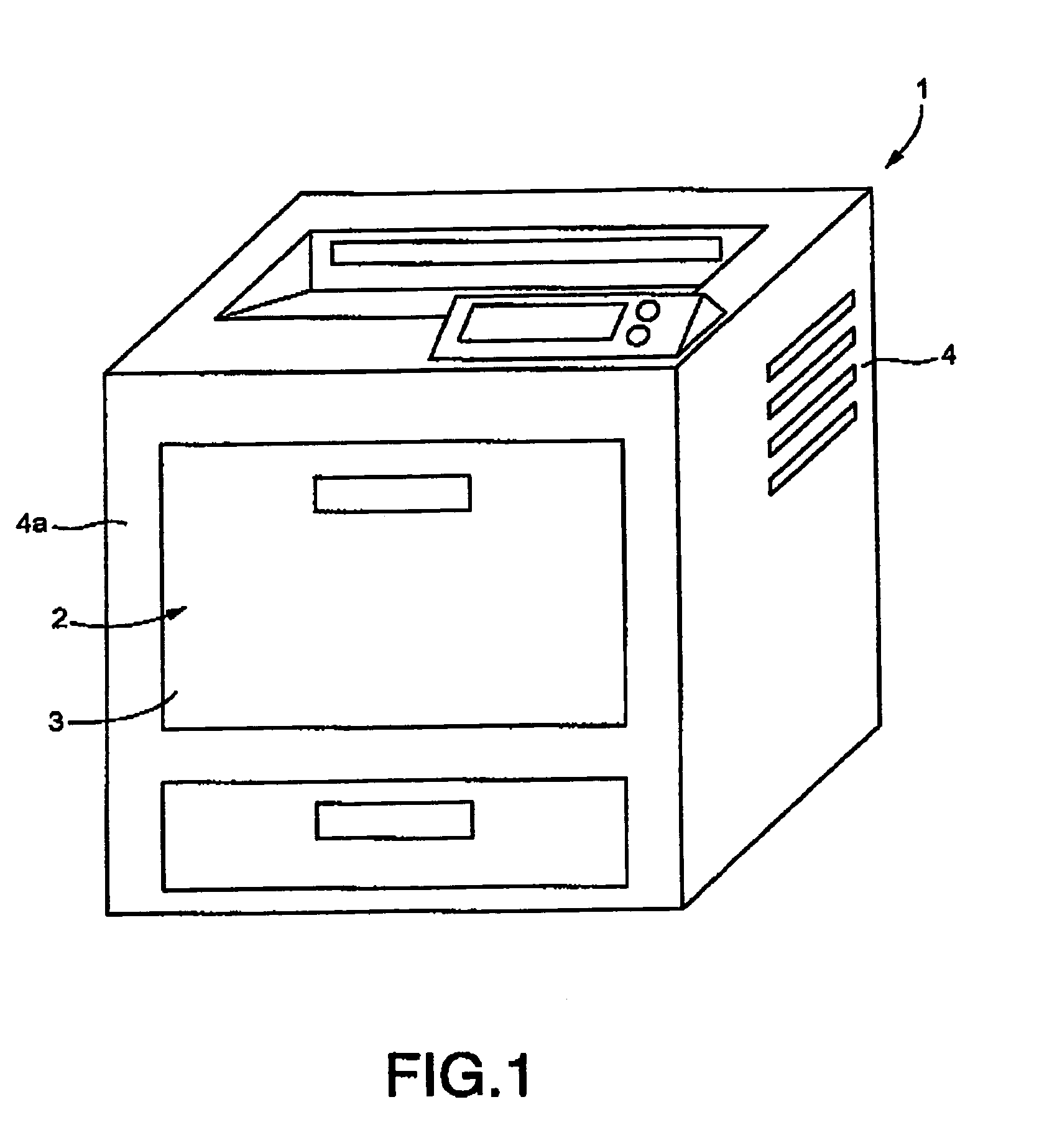
[0123]FIG. 1 shows in perspective view a laser printer 1 as an image forming apparatus having a sheet feeding unit constructed in accordance with the present invention.

[0124]The laser printer 1 has a body 4 which has a front panel 4a. The front panel 4a extends approximately vertically. The laser printer 1 includes a sheet feeding unit 2 disposed at the front panel 4a and incorporating a feeder tray 3.

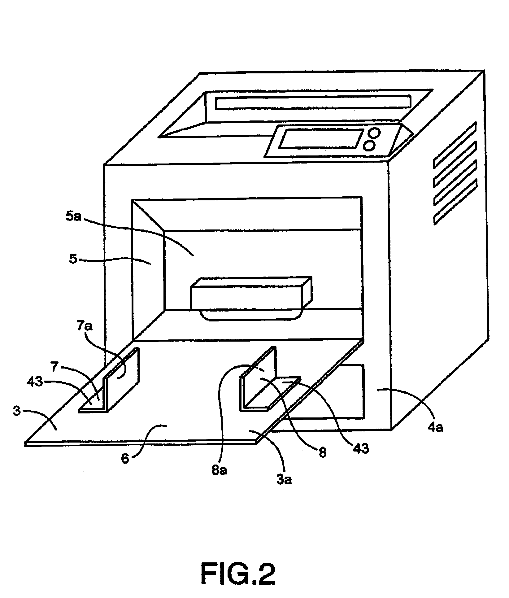
[0125]The feeder tray 3 is configured to be displaceable between a retracted position in which the feeder tray 3 is retracted into an open recess 5 formed at the front panel 4a of the body 4, and an unfolded position in which the feeder tray 3 is protruded outward from the front panel 4.

[0126]FIG. 1 shows in perspective view the laser printer 1 with the feeder tray 3 being in the retracted position, while FIG. 2 shows in perspective view the laser printer 1 with the feeder tray 3 being in the unfolded position allowing loading of a fresh sheet of paper into the feeder tray 3.

[0127]As s...


PUM


Abstract

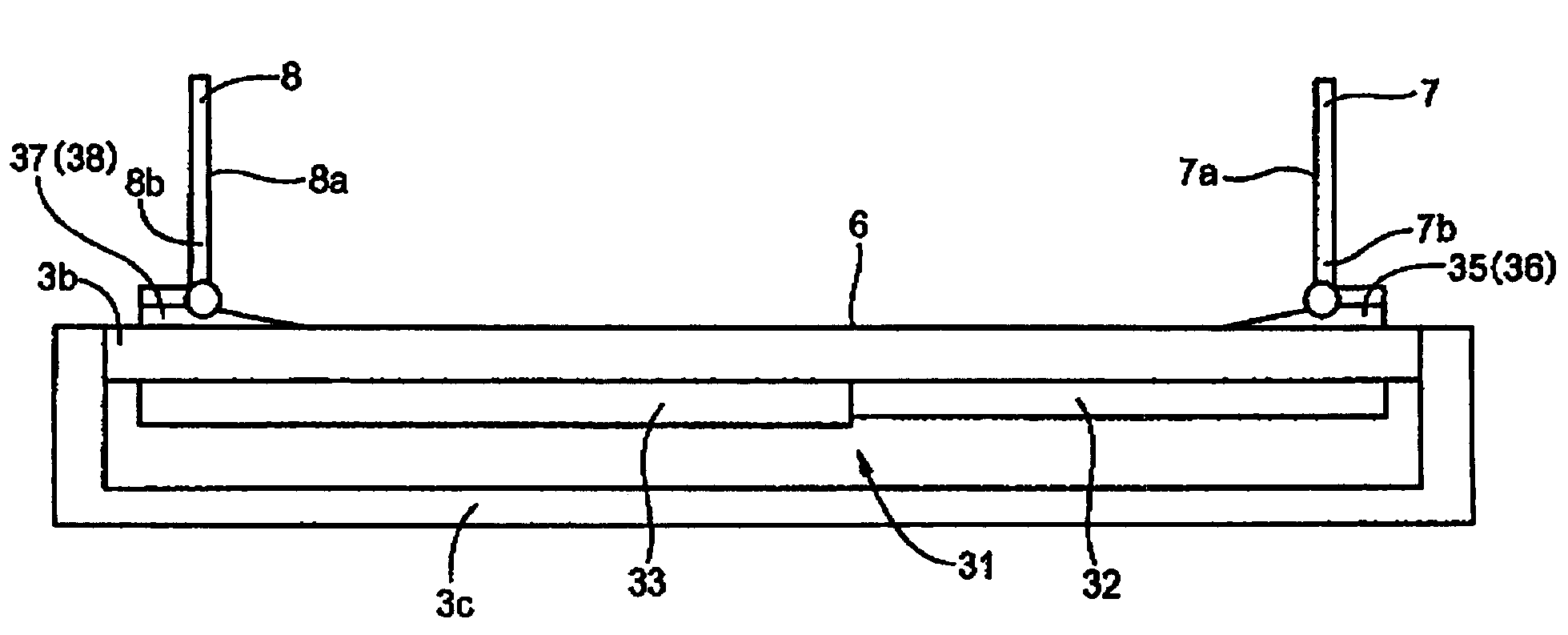
An apparatus for feeding a sheet to a processing device processing the sheet is disclosed that includes: a feeder tray displaceable to a selected one of a retracted position and an unfolded position relative to the processing device, and having a sheet-loaded plane on which the sheet to be fed is to be loaded; a pair of edge guides disposed at the sheet-loaded plane, having a pair of corresponding respective side walls co-extending along a feeding direction of the sheet in opposed relation with each other, to thereby guide lateral edges of the sheet; and a supporting device supporting each of the edge guides pivotably about a pivot axis perpendicular to the feeding direction, to thereby allow the each edge guide to be displaced to a selected one of a standing position on the sheet-loaded plane and an inclined position inclined to the standing position,

Description

[0001]This application is based on Japanese Patent Application No. 2004-006333 filed Jan. 14, 2004, the content of which is incorporated hereinto by reference.CROSS-REFERENCE TO RELATED APPLICATIONS[0002]Not Applicable.BACKGROUND OF THE INVENTION[0003]1. Field of the Invention[0004]The present invention relates to an apparatus for feeding a sheet using edge guides for guiding the lateral edges of the sheet, and more particularly to a technique of reducing a space required for accommodating the apparatus for feeding a sheet.[0005]2. Description of the Related Art[0006]An apparatus for feeding a sheet (hereinafter, referred to as “sheet feeder”) is for use in various applications. One of the applications is an apparatus for forming an image (hereinafter, referred to as “image forming apparatus”) such as a printer. Such a sheet feeder for use in combination with such an image forming apparatus is categorized into one for use in manual feed, and one for use in auto feed. The auto feed a...

Claims


Application Information

Patent Timeline
Patent Type & Authority Patents(United States)
IPC IPC(8): B65H1/00G03G15/00B65H1/04
CPCB65H1/04B65H1/266B65H2404/7414B65H2601/523B65H2405/32B65H2407/21B65H2405/114
Inventor YOKOI, KATSUYUKI
Owner BROTHER KOGYO KK
Learn More