
Micro-optical sensor system for pressure, acceleration, and pressure gradient measurements

a micro-optical sensor and sensor technology, applied in the direction of optical elements, instruments, using wave/particle radiation means, etc., can solve the problems of limiting the application of this type of sensor, affecting the control of sound transmission into enclosed spaces, and increasing the cost of the sensor. achieve the effect of great flexibility

Inactive Publication Date: 2008-09-23
UNIV OF MARYLAND
View PDF34 Cites 34 Cited by
  • Summary
  • Abstract
  • Description
  • Claims
  • Application Information

AI Technical Summary

Benefits of technology

The system provides a wide bandwidth for acoustic and vibration measurements from 50 Hz to 7.5 KHz, offering high sensitivity and flexibility, suitable for active structural acoustic control and vibration control, and is compact and less sensitive to environmental factors.

Problems solved by technology

In the design of modern transportation vehicles, structural vibration and interior noise have become important problems that must be addressed.
For example, control of sound transmission into enclosed spaces is an important issue for helicopter systems.
However, the sensor bandwidth was found to be limited, and in addition, the sensor was found to have low sensitivity due to the high Young's modules of silica resulting in “acoustically induced strains” which also limits the application of this type of sensors.
Currently, there are no commercially available micro-scale fiber optic sensor systems that can be used for these measurements, since the current technology is generally directed toward condenser microphones.
However, the complexity and bulkiness of known velocity microphones makes them difficult to use effectively in ASAC systems.
However, these sensors make use of a thermal effect, and they disadvantageously need high operating temperatures.

Method used


Image

  • Micro-optical sensor system for pressure, acceleration, and pressure gradient measurements
  • Micro-optical sensor system for pressure, acceleration, and pressure gradient measurements
  • Micro-optical sensor system for pressure, acceleration, and pressure gradient measurements

Examples


Embodiment Construction

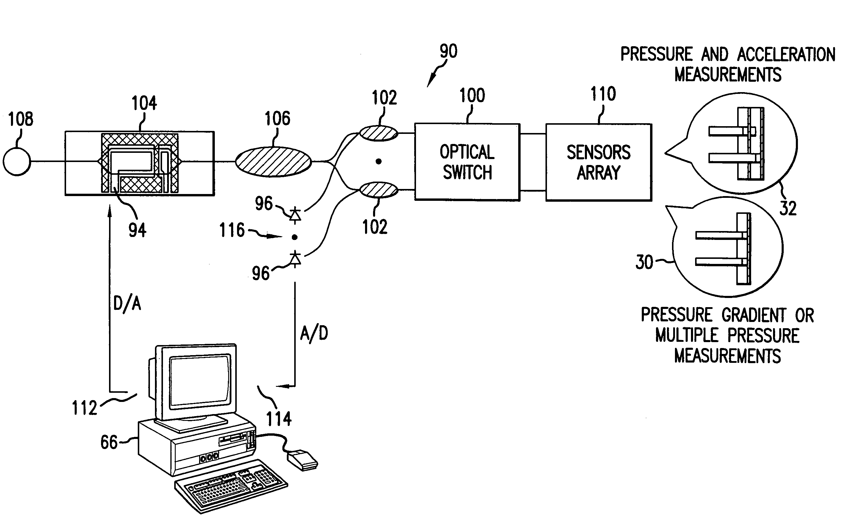
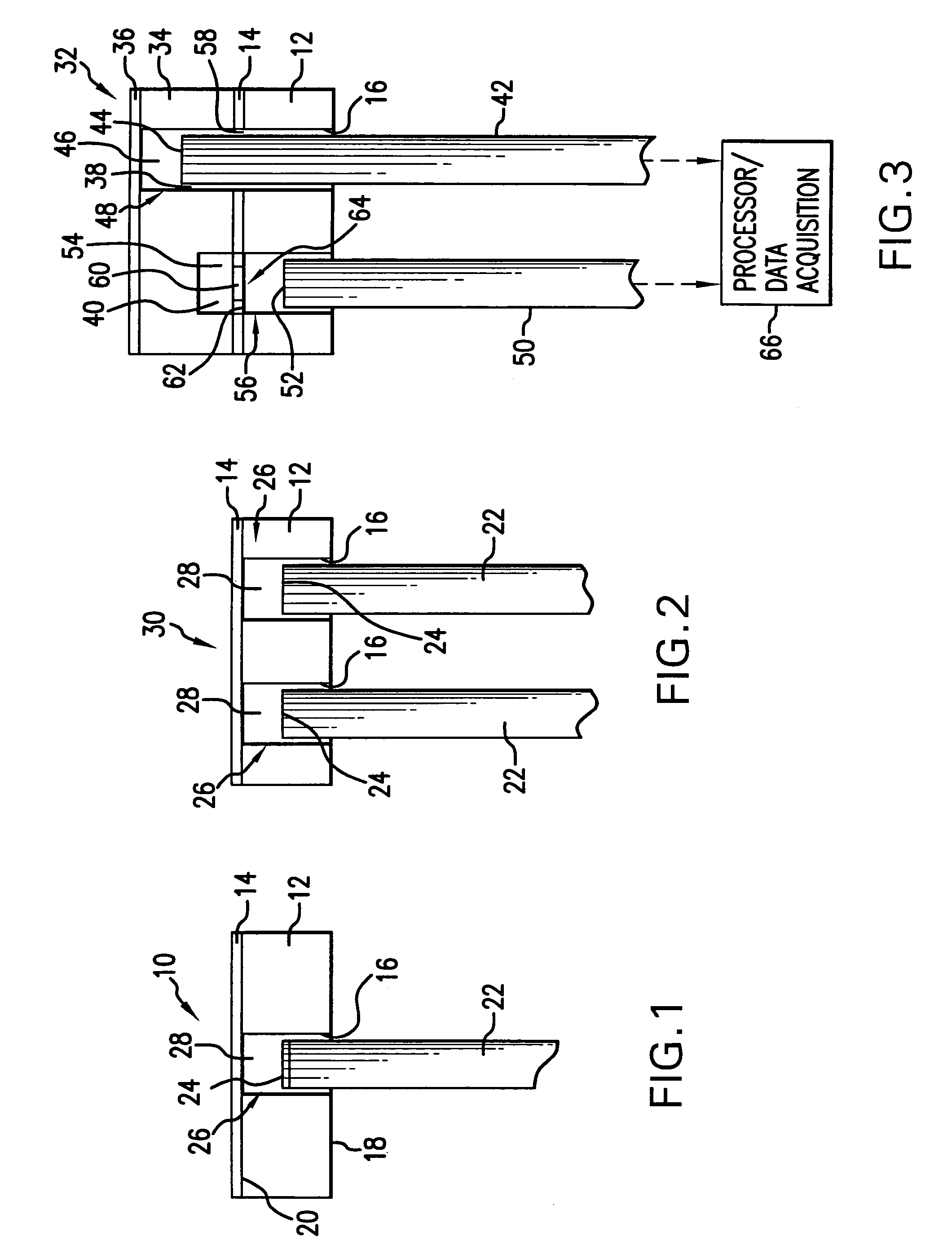
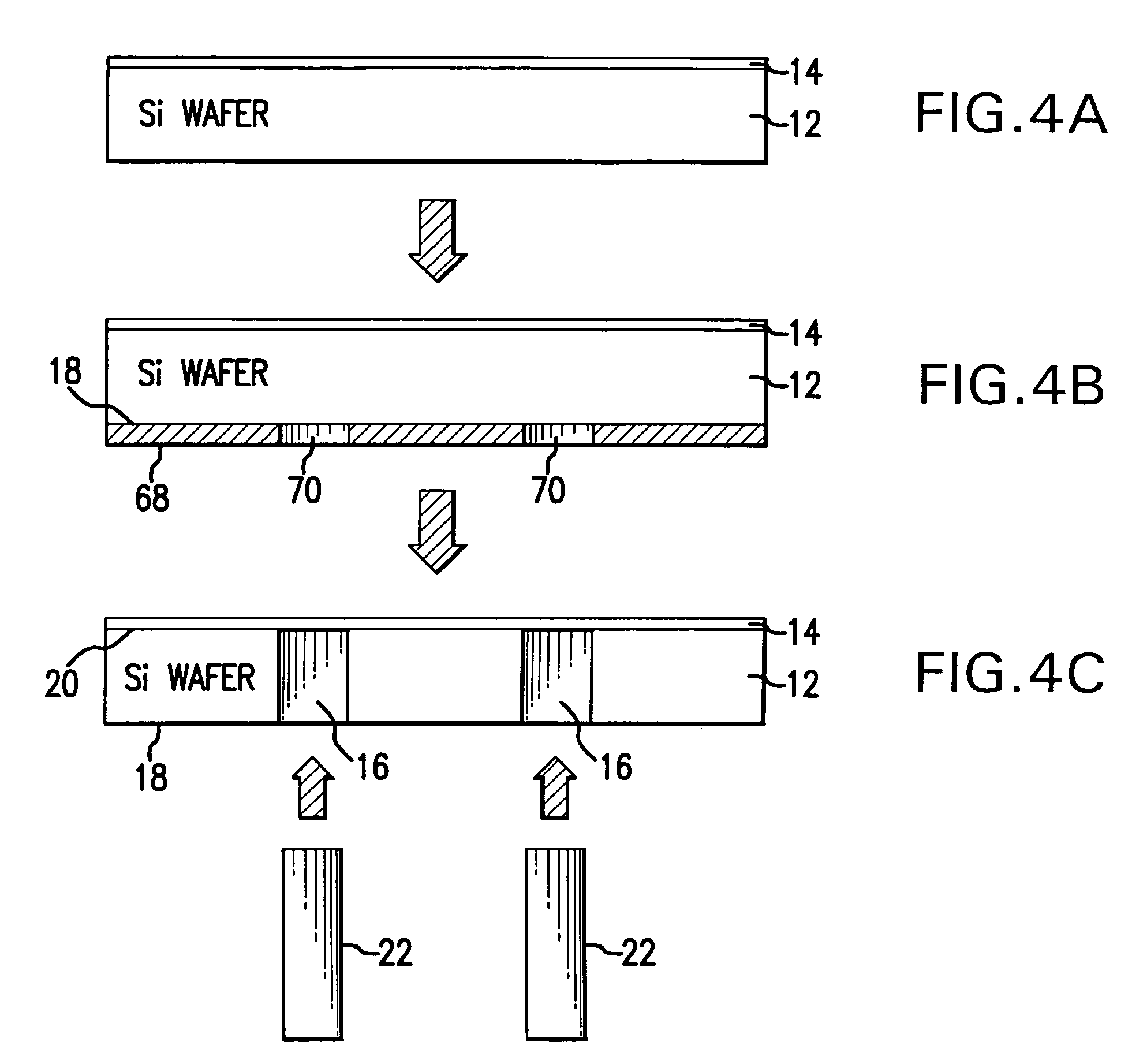
[0067]Referring to FIG. 1, a pressure sensor 10 of the present invention is shown which includes a silicon wafer 12 with a thin layer 14 formed of a metal or a polymer with a thickness in the range of 100 nm-1 μm, referred hereinto as a diaphragm layer 14. The silicon wafer 12 is patterned to form a fiber guide 16 which extends through the width of the silicon wafer 12 between a bottom surface 18 and the top surface 20 thereof. An optical fiber 22 is received in the fiber guide 16 with the tip 24 displaced from the diaphragm layer 14 by a predetermined distance which may be adjusted as needed. The fiber tip 24, as well as the diaphragm layer 14, are formed optically reflective for the purposes described infra herein. In the pressure sensor 10, as shown in FIG. 1, a sensing fiber tip based interferometer 26 is formed and this interferometer has a Fabry-Perot cavity 28 between the fiber tip 24 and the diaphragm layer 14. The optically reflective fiber tip and the diaphragm 14 form a p...


PUM


Abstract

A micro-optical fiber tip based sensor system for pressure, acceleration, and pressure gradient measurements in a wide bandwidth, the design of which allows for multiplexity of the input side of the system is based on micro-electromechanical fabrication techniques. The optical portion of the system is based on low coherence fiber-optic interferometry techniques which has a sensor Fabry-Perot interferometer and a read-out interferometer combination that allows a high dynamic range and low sensitivity to the wavelength fluctuation of the light source. A phase modulation and demodulation scheme takes advantage of the Integrated Optical Circuit phase modulator and multi-step phase-stepping algorithm for providing high frequency and real time phase signal demodulation. The system includes fiber tip based Fabry-Perot sensors each of which has a diaphragm that is used as a transducer.

Description

REFERENCE TO RELATED APPLICATIONS[0001]This Utility Patent Application is based on a Provisional Patent Application No. 60 / 569,296 filed 7 May 2004, and is a Continuation-in-Part of Utility patent application Ser. No. 10 / 270,277 filed 15 Oct. 2002 now U.S. Pat. No. 6,901,176.FIELD OF THE INVENTION[0002]The present invention relates to pressure, acceleration, and pressure gradient measurements; and in particular, to micro-optical sensor systems for measurements applicable for surveillance applications, health monitoring of civil structures, diagnostic applications in hostile environments, monitoring in extreme environments such as oil wells, acoustic emission measurements in computer systems, pressure measurements in ignition chambers of automobiles, distributed pressure sensor arrays for adaptive wing structures, and distributed acoustic pressure array panels for acoustic measurements in concert halls, conference rooms, and the like.[0003]Additionally, micro-scale sensors may be use...

Claims


Application Information

Patent Timeline
Patent Type & Authority Patents(United States)
IPC IPC(8): G01B9/02G02B6/00G01D5/353G01H9/00G02B6/34
CPCG01D5/35303G01H9/006G02B6/29358G02B6/2935
Inventor YU, MIAOBALACHANDRAN, BALAKUMAR
Owner UNIV OF MARYLAND
Learn More