Controllable pixel border for a negative mode passive matrix display device

a passive matrix display device and controllable pixel border technology, applied in the field of flat panel display screen technology, can solve the problems of inacceptable solution and difficult reading of edge displayed characters by users, and achieve the effect of improving viewability and maximising the use of screen pixels

Inactive Publication Date: 2008-09-16
QUALCOMM INC
View PDF38 Cites 14 Cited by
  • Summary
  • Abstract
  • Description
  • Claims
  • Application Information

AI Technical Summary

Benefits of technology

[0011]Accordingly, embodiments of the present invention provide an electronic device, e.g., a cell phone, portable computer system, PDA, electronic pager, etc., having a screen that makes maximal use of the available screen pixels while eliminating the problems associated with edge displayed characters in display formats where the pixels of the character are of the same or similar color as the edge region. Embodiments of the present invention are particularly useful in negative mode passive matrix LCD displays that utilize a brighter background and a darker foreground. Embodiments provide the above benefits while being compatible with standard display screen dimensions, formats and driver circuitry. Embodiments of the present invention therefore provide a small display screen with improved viewability, especially at the edge locations. The present invention provides these advantages and others not specifically mentioned above but described in the sections to follow.
[0012]A display device is described herein having a display matrix including a pixel border of width x and located around the edge locations of the matrix for improved viewability. In particular, the border region can be several pixels wide, e.g., 1<x<5. In one embodiment, the border region is two pixels wide and surrounds a display region in which images are generated from a frame buffer memory. In one implementation, both the border region and the display region are implemented using a negative display mode passive display matrix using supertwisted nematic liquid crystal display (LCD) technology. Other passive matrix techniques could also be used in addition to LCD technology, such as, electronic paper, electronic ink, or microelectromechanical machine systems (MEMS), etc.
[0013]In one embodiment, the pixels of the border region are controllable between an on state and an off state and have an adjustable threshold voltage level. The threshold voltage level can originate from a gray scale bias circuit which can be controlled by a contrast adjustment. This allows the border brightness and the background brightness to be matched in response to contrast adjustments. In one embodiment, the display screen is a negative mode display in which the pixels are normally black when off. The pixel border is useful in providing contrast in display modes having a white background with black characters displayed therein. In these display modes, the border region is uniformly turned on to provide a white border. As discussed above, the white border adjusts with the background brightness in response to contrast adjustments. The present invention can be applied in either monochrome or color displays. The pixel border is also advantageous in that it can be used with conventional character generation processes of the operating system of the computer used to drive the display screen. In one embodiment, the novel display can be used within a portable computer system or other portable electronic device.

Problems solved by technology

This makes reading the edge displayed character very difficult for a user.
However, this solution is not acceptable in the case of a small display screen where every pixel is needed for image and information presentation.

Method used


Image

  • Controllable pixel border for a negative mode passive matrix display device
  • Controllable pixel border for a negative mode passive matrix display device
  • Controllable pixel border for a negative mode passive matrix display device

Examples


Embodiment Construction

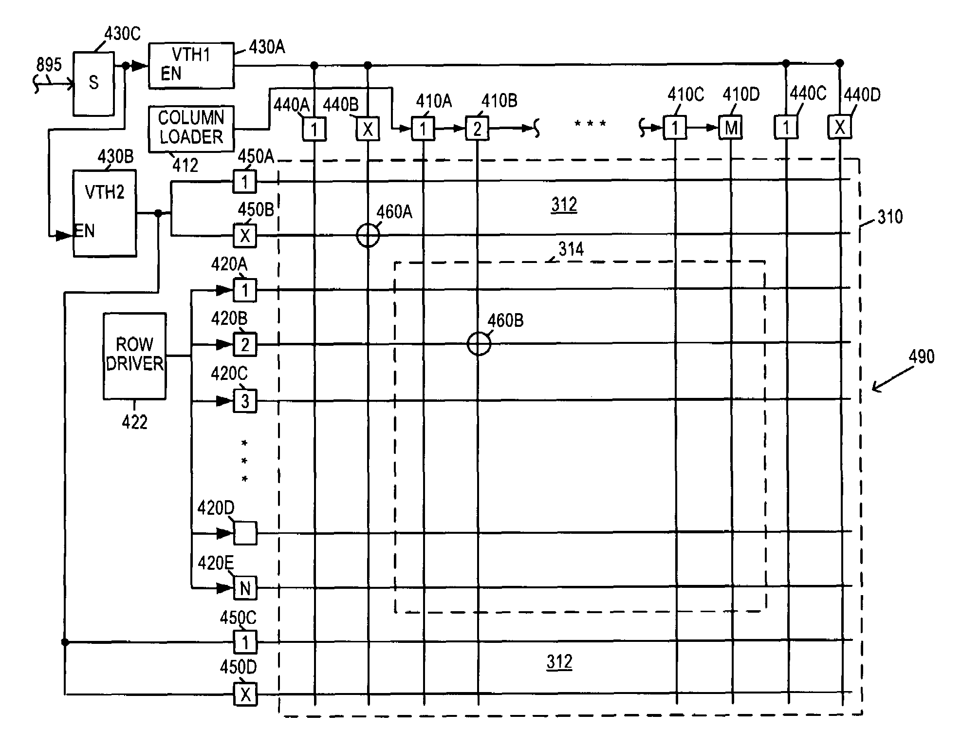
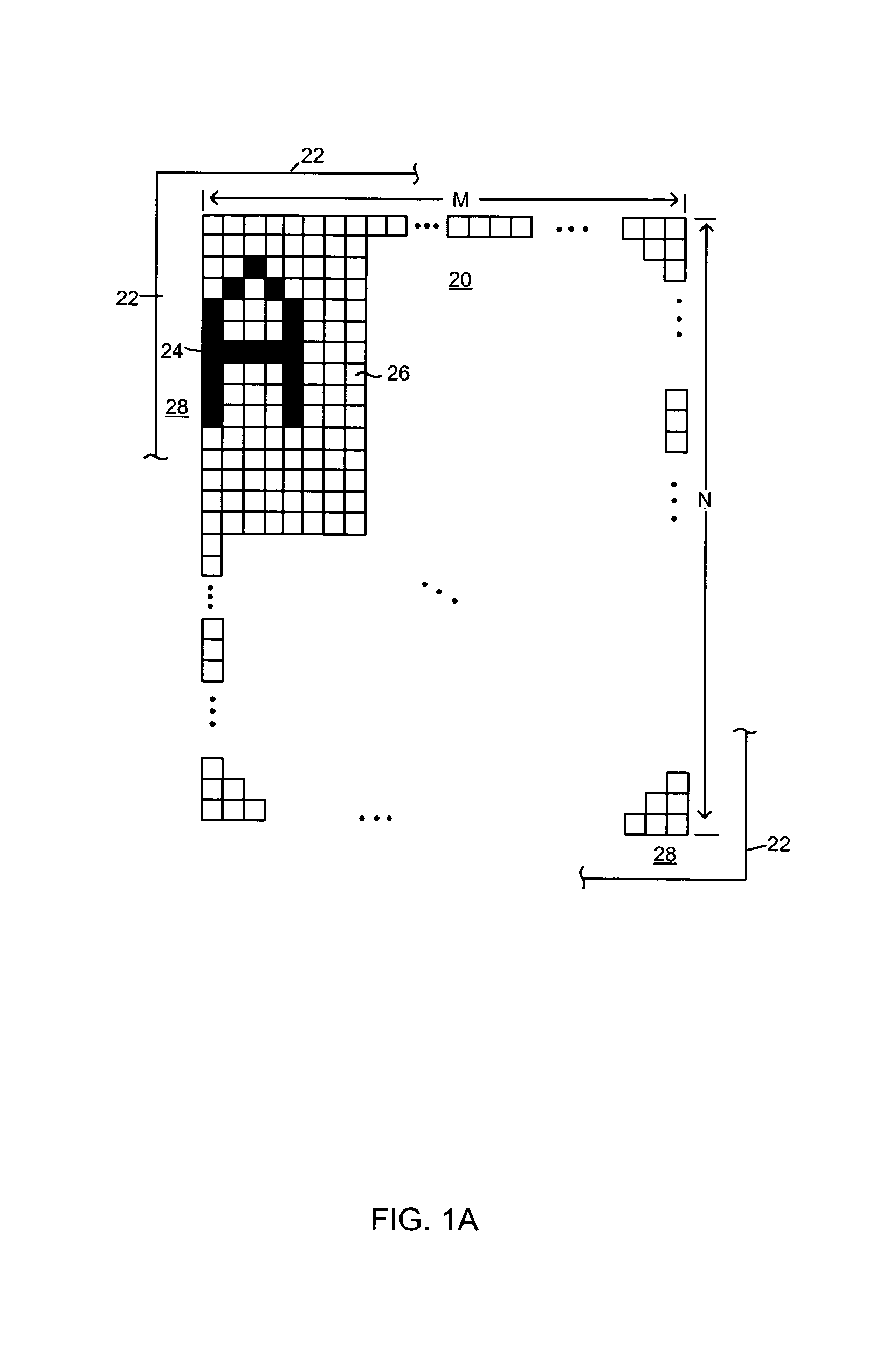
[0035]In the following detailed description of the present invention, a controllable pixel border for a negative display mode passive matrix display screen which provides contrast improvement for increased viewability of edge-displayed characters, numerous specific details are set forth in order to provide a thorough understanding of the present invention. However, it will be recognized by one skilled in the art that the present invention may be practiced without these specific details or with equivalents thereof. In other instances, well known methods, procedures, components, and circuits have not been described in detail as not to unnecessarily obscure aspects of the present invention.

[0036]The following co-pending application is hereby incorporated by reference, Ser. No. 09 / 709,142, by Canova, et al., entitled “Pixel Border for Improved Viewability of a Display Device,” filed Nov. 8, 2000 and assigned to the assignee of the present invention.

Exemplary Portable Electronic Device P...


PUM


Abstract

A display device having a display matrix including a pixel border of width x and located around the edge locations of the matrix for improved viewability. In particular, the border can be several pixels wide, e.g., 1<x<5. In one embodiment, the border region is two pixels wide and surrounds a display region in which images are generated from a frame buffer memory. Both the border region and the display region are implemented using a negative mode passive display matrix using liquid crystal display (LCD) technology. The pixels of the border are controllable between an on state and an off state and have an adjustable threshold voltage level. In one embodiment, the display screen is a negative mode display in which the pixels are normally black when off. The pixel border is useful in providing contrast in display modes having a white background with black characters displayed therein.

Description

RELATED US APPLICATION[0001]The present application is a continuation-in-part application of U.S. application Ser. No. 09 / 709,142, by Canova, et al., entitled “Pixel Border for Improved Viewability of a Display Device,” filed Nov. 8, 2000 now U.S. Pat. No. 6,961,029 and which is hereby incorporated by reference.BACKGROUND OF THE INVENTION[0002]1. Field of the Invention[0003]The present invention relates to the field of display screen technology. More specifically, embodiments of the present invention relate to flat panel display screens that are useful in conjunction with portable electronic devices.[0004]2. Related Art[0005]As the components required to build a computer system have reduced in size, new categories of computer systems have emerged. One of the new categories of computer systems is the “palmtop” computer system. A palmtop computer system is a computer that is small enough to be held in the hand of a user and can therefore be “palm-sized.” Most palmtop computer systems ...

Claims


Application Information

Patent Timeline
IPC IPC(8): G09G5/02G09G3/20G09G3/36
CPCG09G3/3622G09G5/026G09G3/2074G09G2340/145G09G2310/0232G09G2320/029G09G2320/066G09G5/40
Inventor GETTEMY, SHAWN R.FRASER, SHERRIDYTHELUM, DAVID W.
Owner QUALCOMM INC
Why Eureka
Try Eureka