
Membrane-mediated electropolishing

a membrane-mediated electropolishing and electropolishing technology, applied in the direction of flexible wheel, manufacturing tools, lapping machines, etc., can solve the problems of incompatible mechanically fragile materials, high cost of cmp, and hazardous waste products

Inactive Publication Date: 2008-09-09
EI DU PONT DE NEMOURS & CO
View PDF16 Cites 11 Cited by
  • Summary
  • Abstract
  • Description
  • Claims
  • Application Information

AI Technical Summary

Benefits of technology

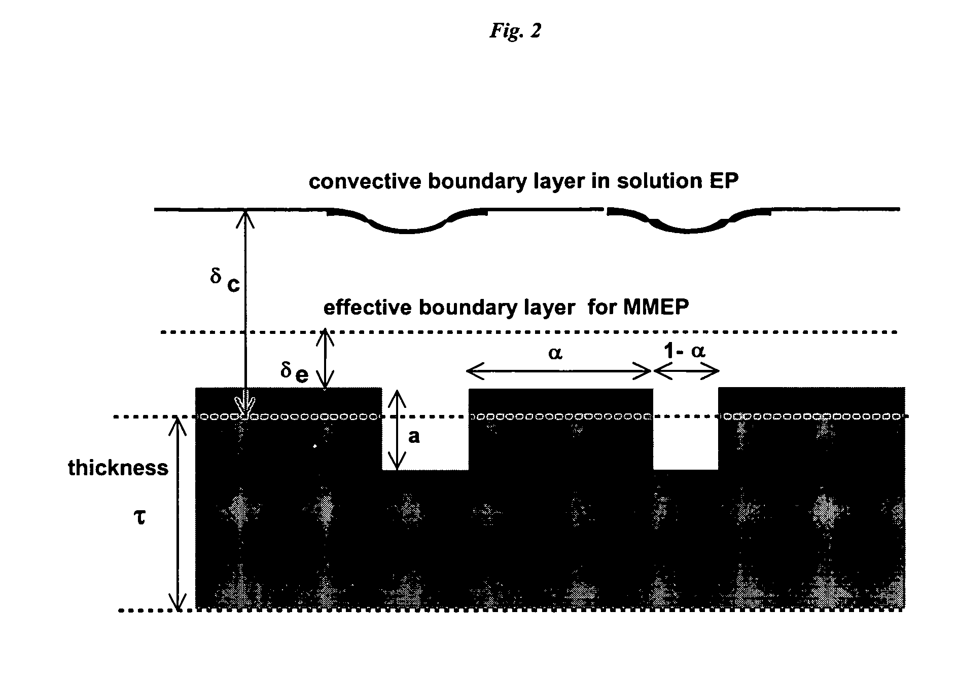
[0033]In preferred embodiments of the invention, the conductive electrolyte composition has a conductivity greater than about 100 mS / cm and comprises water, an acid, and a metal salt. Alternatively, the conductive electrolyte composition comprises water and acetonitrile. In either case, the low-conductivity fluid advantageously has a conductivity much lower than that of the conductive electrolyte composition, generally at least 100 times lower than, and preferably at least 1000 times lower than said conductive electrolyte composition (e.g., the low-conductivity fluid has a conductivity below about 200 μS / cm or below about 100 μS / cm). The method can efficiently planarize most structures on a metal-containing integrated circuit surface if the low-conductivity fluid has a conductivity between about 0.5 μS / cm and about 150 μS / cm. For structures with very large λ, the low-conductivity fluid advantageously has a conductivity between about 1 μS / cm and about 10 μS / cm.
[0121]2) there are substantially no scratching and particulate defects on the polished surface after polishing, which affect component reliability; and

Problems solved by technology

However, CMP is a costly process, generates hazardous waste products, and is incompatible with the mechanically fragile materials currently under development for improved dielectric layers.

Method used


Image

  • Membrane-mediated electropolishing
  • Membrane-mediated electropolishing
  • Membrane-mediated electropolishing

Examples


example 1

Membrane-Mediated Electropolishing of Cu Coupons

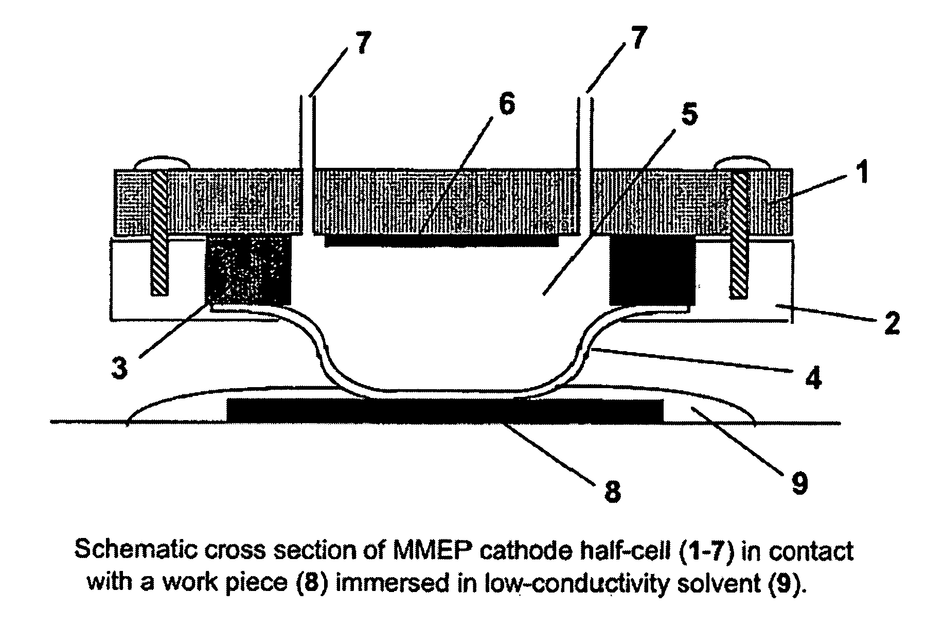
[0457]A cathode half-cell was constructed for membrane-mediated electropolishing (MMEP) whose cross-section is shown schematically in FIG. 3. The half-cell comprised a polypropylene base (1) bolted to a stainless steel faceplate (2) which framed an opening approximately 1.0 cm×2.5 cm. This opening was covered by a piece of Nafion® membrane (4) (NE1135, 3.5 mil thick) sealed against the faceplate by means of a silicone rubber gasket (3) approximately 0.5 cm thick. A piece of copper foil (6) was sealed to the base and electrically connected to a wire on the outside of the half-cell. The cavity (5) defined by base, gasket and membrane contained two ports (7) connected to Teflon® tubing (OD 1 / 16″) through which the electrolyte (0.2 M copper sulfate in 40% phosphoric acid) was continuously re-circulated by means of a peristaltic pump (not shown) from an external reservoir. Electrolyte was pumped through the half-cell at approximately 10 ml / ...

example 2

Comparison of Membrane-Mediated and Conventional Electropolishing

[0461]Two copper coupons (1.5″×2.0″) were milled as in Example 1 and then masked with tape so that only an area of 0.71 cm2 was exposed. One of these coupons was polished by MMEP using the same procedure as in Example 1. The second coupon was polished by the conventional electropolishing (EP) method. For EP a silicone rubber gasket ⅜″ thick was used to separate the work piece from a sheet of copper foil which served as the cathode. A cylindrical cavity in this gasket provided a volume between the work piece and cathode filled by electrolyte solution that was continuously pumped through cavity. The area of work piece exposed to electrolyte in the EP cell was the same as that polished by the MMEP process. The same electrolyte (0.2 M Copper sulfate in 40% phosphoric acid) and the same pumping rate was used in both sets of polishing experiments. The root-mean-square roughness Rg was measured by profilometry and the results...

example 3

Comparison of Membrane-Mediated and Conventional Electropolishing for Planarizing Surfaces with Large-λ Features

[0464]A copper coupon was polished to a mirror finish using jeweler's rouge, then laminated to a dry-film photoresist (Riston® 9415, E.I. Dupont de Nemours and Company, Inc., Wilmington, Del.). The photoresist film was covered with a lithographic negative patterned with 100 micron lines interspersed with 100 micron spaces, and then exposed and developed under conditions recommended by the manufacturer (DuPont Riston® Printed Circuit Materials, RD 1, New James St., Towanda, Pa. USA 18848-9784). The exposed areas on the coupon were etched for 1 minute in a 5% solution of sodium monopersulfate (Sigma-Aldrich, Milwaukee, Wis.), followed by conventional electropolishing at 2.0 V and 1.5 coul / cm2 (as described in Example 2). The resist mask was then removed by soaking in dichloromethane, leaving a corrugated surface with alternating 100 micron trenches and 100 micron plateaus. T...


PUM

PropertyMeasurementUnit
conductivityaaaaaaaaaa

Abstract

This invention provides a membrane-mediated electropolishing process for polishing and / or planarizing metal work pieces. The work piece is wetted with a low-conductivity fluid. The wetted work piece is contacted with a first side of a charge-selective ion-conducting membrane, wherein the second side contacts a conductive electrolyte solution in electrical contact with a cathode. Current flow between the cathode and the work piece electropolishes metal from the work piece. This process can be used for both pure metals and alloys, and provides several significant advantages over conventional electropolishing processes. This invention also provides an apparatus useful in the membrane-mediated electropolishing process.

Description

CROSS-REFERENCE TO RELATED APPLICATIONS[0001]This application claims priority to the following: U.S. Provisional Patent Application No. 60 / 611,699, filed on Sep. 22, 2004; U.S. Provisional Patent Application No. 60 / 570,967, filed on May 14, 2004; U.S. Provisional Patent Application No. 60 / 546,192, filed on Feb. 23, 2004; U.S. Provisional Patent Application No. 60 / 546,198, filed on Feb. 23, 2004; and U.S. Provisional Patent Application No. 60 / 516,235, filed on Oct. 31, 2003, all by Stephen Mazur and Charles E. Jackson; the disclosures of which are incorporated herein by reference hereto for all purposes.STATEMENT REGARDING FEDERALLY SPONSORED RESEARCH OR DEVELOPMENT[0002]N / AINCORPORATION-BY-REFERENCE OF MATERIAL SUBMITTED ON A COMPACT DISC[0003]N / ASEQUENCE LISTING[0004]N / AFIELD OF THE INVENTION[0005]This invention relates to a process for electropolishing metal surfaces, and more specifically to a membrane mediated electropolishing process, wherein a conductive electrolyte contacts a...

Claims


Application Information

Patent Timeline
Patent Type & Authority Patents(United States)
IPC IPC(8): C25F3/14B23H3/10B23H5/06C25F3/22C25F7/00B23H5/08B24B37/04B24D13/14C25F3/16H01L21/321
CPCB23H5/08B24B37/042B24B37/046H01L21/32125C25F3/16H01L21/32115C25F3/02C25F3/00
Inventor MAZUR, STEPHENJACKSON, JR., CHARLES E.
Owner EI DU PONT DE NEMOURS & CO
Learn More