Fuel injector having a separable armature and pintle
a fuel injector and separable technology, applied in the field of fuel injectors, can solve the problems of high cost of piezo-stack and driver, high volume applications, and complex control systems, and achieve the effects of reducing the risk of valve bounce at the injector closing, reducing the risk of valve bounce, and greatly reducing theinertia of the pintl
- Summary
- Abstract
- Description
- Claims
- Application Information
AI Technical Summary
Benefits of technology
Problems solved by technology
Method used
Image
Examples
first embodiment
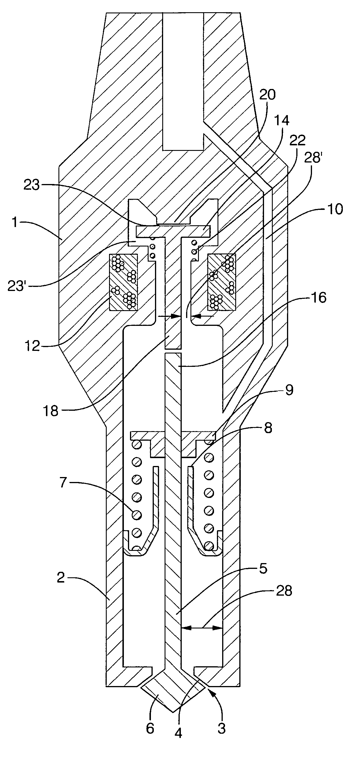
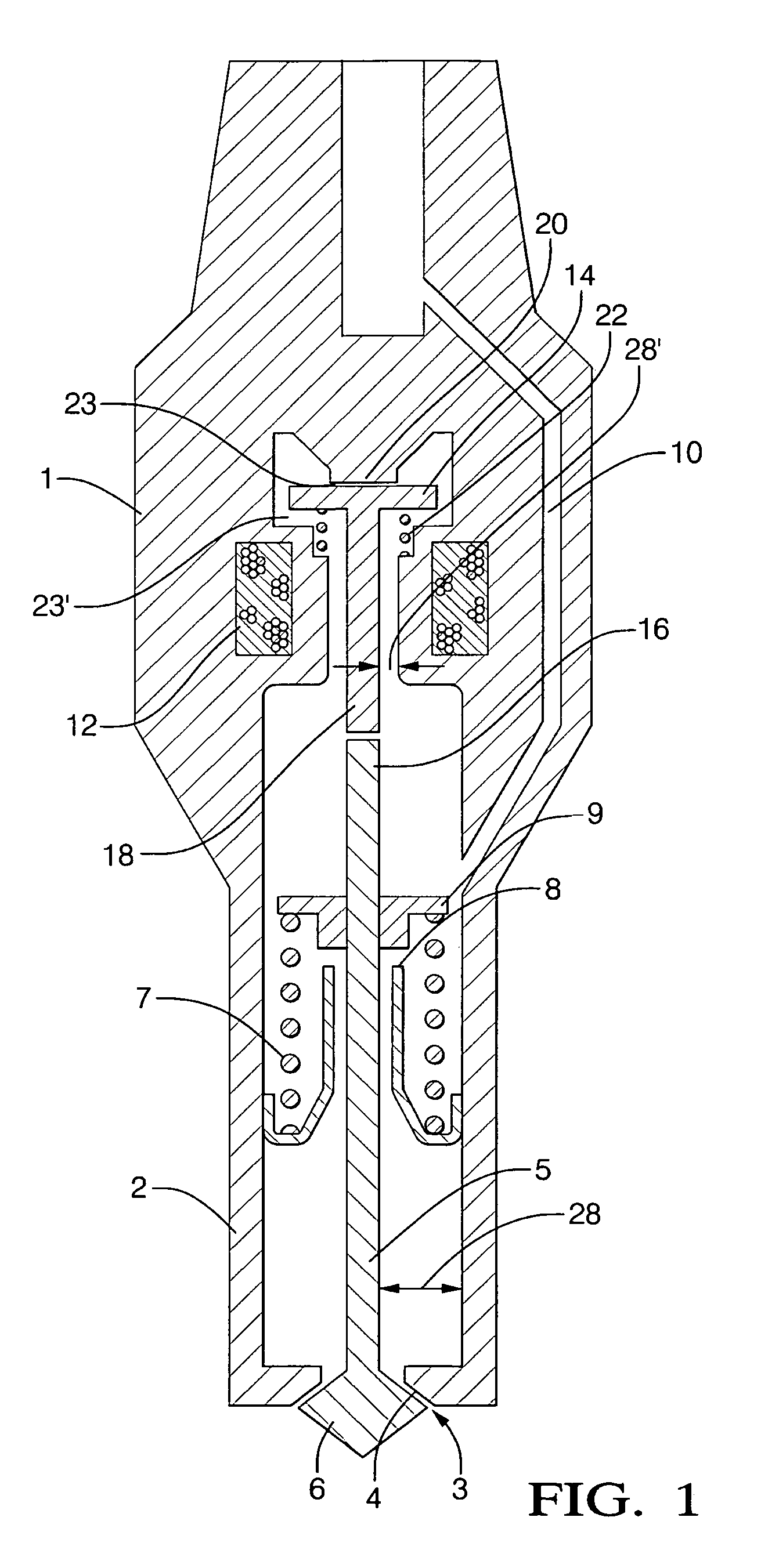
[0020]A fuel injector according to the present invention is shown in FIG. 1. The fuel injector comprises an injector body 1 having a tip portion 2 having a spray aperture 3 at a distal end thereof. An outwardly opening valve pintle 5 extends within the tip portion 2, the pintle 5 having a head portion 6 engageable with a valve seat 4 surrounding the spray aperture 3 to close the spray aperture 3.
[0021]The pintle 5 is axially moveable within the injector body 1 between a retracted position wherein the head portion 6 engages the valve seat 4 and an extended position wherein the head portion 6 is spaced from the valve seat 4. A return spring 7 is mounted within the tip portion, biasing the pintle 5 towards its retracted position. An end stop 8 mounted on the injector housing 1 cooperates with a collar 9 on the pintle to limit the extension of the pintle 5 and define the extended position of the pintle 5.
[0022]The interior of the tip portion 2 of the injector body 1 communicates with an...
second embodiment
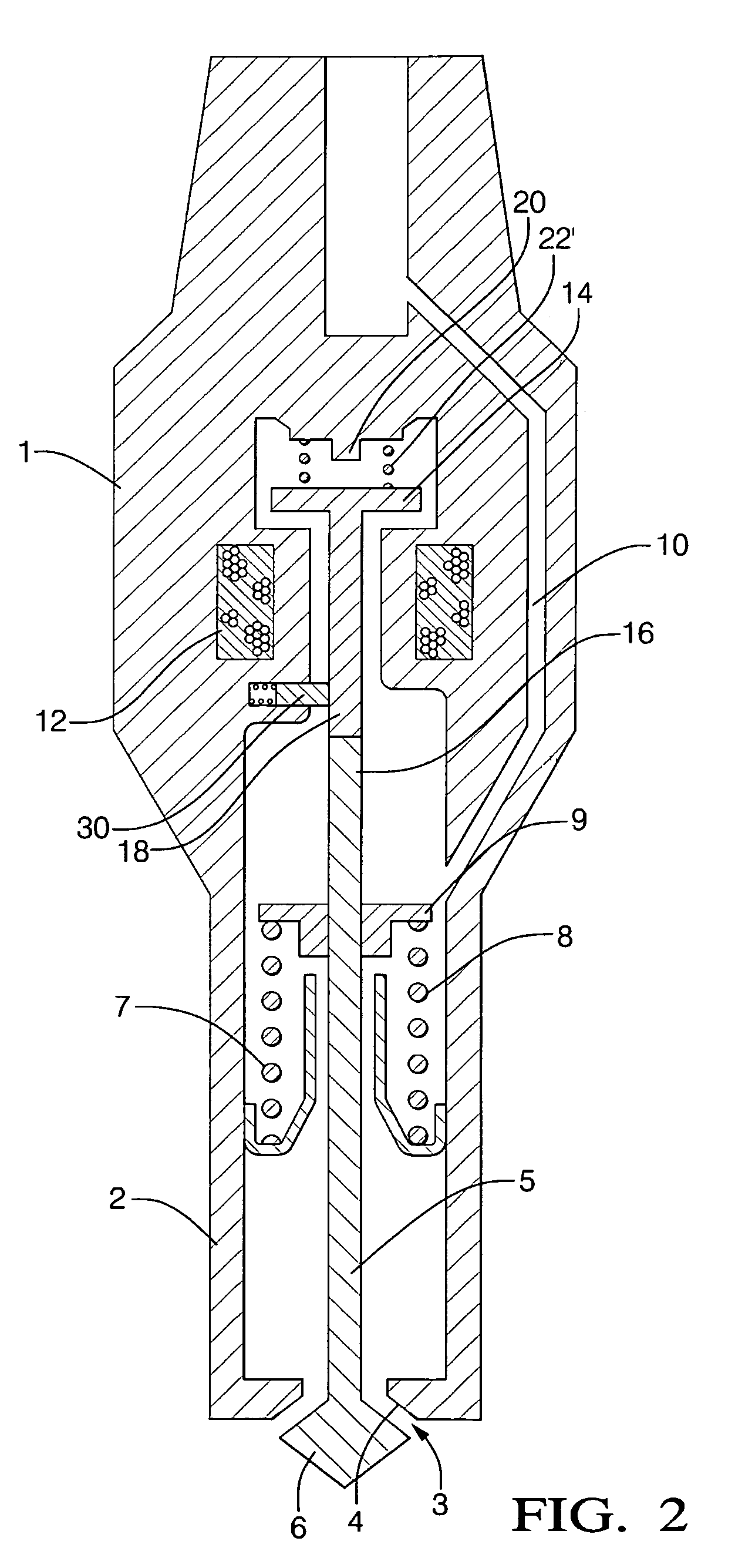
[0031]In a second embodiment, shown in FIG. 2, the armature return spring 22′ is provided between the armature 14 and the upper stop 20 to bias the armature 14 into contact with the pintle 5. In such embodiment, the armature return spring 22′ can be selected to calibrate the injector, such spring acting against the main return spring 7 to provide a force acting on the pintle 5 in a valve opening direction.
[0032]In an alternative embodiment (not shown) the armature may be upwardly biased away from the pintle, as in the embodiment shown in FIG. 1. However, instead of locating the armature return spring between the housing and the armature—as shown in FIG. 1—the armature return spring may act between the pintle 5 and the lower portion 18 of the armature 14, such that the return spring is referenced to the pintle 5 rather than the housing 1. By locating the armature return spring adjacent the pintle 5, an upward bias is provided that does not reduce the available armature magnetic force...
PUM
 Abstract
Description
Claims
Application Information
 - R&D
- Intellectual Property
- Life Sciences
- Materials
- Tech Scout
- Unparalleled Data Quality
- Higher Quality Content
- 60% Fewer Hallucinations
Browse by: Latest US Patents, China's latest patents, Technical Efficacy Thesaurus, Application Domain, Technology Topic, Popular Technical Reports.
© 2025 PatSnap. All rights reserved.Legal|Privacy policy|Modern Slavery Act Transparency Statement|Sitemap|About US| Contact US: help@patsnap.com


