
Control method for an exhaust gas purification system and an exhaust gas purification system

a technology of exhaust gas purification system and control method, which is applied in electrical control, machine/engine, separation process, etc., can solve the problems of excessive oil dilution, inability to re-regenerate filters, and continual accumulation of pm in filters, so as to prevent excessive oil dilution, improve the operability of drivers, and reduce the frequency of manual regeneration

Active Publication Date: 2008-09-09
ISUZU MOTORS LTD
View PDF15 Cites 22 Cited by
  • Summary
  • Abstract
  • Description
  • Claims
  • Application Information

AI Technical Summary

Benefits of technology

[0019]It is an object of the present invention to provide an exhaust gas purification system control method and an exhaust gas purification system capable of prompting a driver to stop a vehicle and perform manual regeneration by operating a manual regeneration switch in accordance with a warning such as flashing of an indicator lamp in the case where it is detected that a detected collecting quantity is larger than the predetermined judgment collecting quantity with regard to regeneration of the continuous regeneration type DPF device or greatly decreasing the frequency of manual regeneration to improve the operability for a driver, and solving an oil dilution problem due to a large amount of unburned fuel injected for DPF regeneration in an exhaust gas purification system for performing automatic regeneration to be automatically performed while a vehicle travels.
[0037]According to the control method for an exhaust gas purification system and an exhaust gas purification system of the present invention, when detecting that a detected collecting quantity is larger than a predetermined judgment collecting quantity with regard to regeneration of a continuous regeneration type DPF device, manual regeneration performed when a driver stops a vehicle in accordance with a warning such as flashing of an indicator lamp and performs forced regeneration by operating a manual regeneration switch is alternatively used with automatic traveling regeneration for automatically performing forced regeneration while a vehicle travels in accordance with a number-of-regeneration-times coefficient serving as an index of the number of regeneration times to a travel distance. Therefore, it is possible to prevent oil from being excessively diluted while corresponding to a change of traveling patterns of a vehicle and avoiding the manual regeneration whose convenience is inferior in using the vehicle.
[0038]Moreover, it is possible to select automatic traveling regeneration while diluted oil quantity is small and select manual regeneration only when the diluted oil quantity is large. Therefore, it is possible to extremely decrease the frequency of manual regeneration in accordance with the operation of the manual regeneration switch and improve the operability for a driver.
[0039]Furthermore, it is possible to control the degree of dilution of oil by unburned fuel to be added by post injection. Therefore, it is possible to improve the durability of an engine and secure the reliability of the engine.

Problems solved by technology

However, these continuous regeneration type DPF devices also cause the problem of exhaust pressure rise by the clogging of this filter.
However, in the case of low exhaust gas temperature and in an operating condition of an internal combustion engine where the emission of NO is low, for example, in the case where the low exhaust gas temperature state such as idling of internal combustion engine, low load / low speed operation continues, the oxidation reaction is not stimulated as the exhaust gas temperature is low, the catalyst temperature lowers and the catalyst is not activated and, moreover, NO lacks.
Consequently, the aforementioned reaction does not occur and the filter can not be regenerated through oxidation of PM.
As a result, PM continues to be accumulated in the filter and the filter clogging progresses.
However, because the fuel for the post injection is not burned in the cylinder of an engine, injected fuel mixes in the oil of the engine through the joint of a piston ring or the like to cause oil dilution due to the fuel.
The oil dilution causes deterioration of the viscosity of the engine oil etc.
Therefore, when fuel dilution of a certain level or more occurs, it influences the durability of the engine and a problem occurs in the reliability of the engine.
Therefore, there is a problem that the fuel dilution quantity cannot be controlled.
Moreover, when the problem of the oil dilution is left as it is, abrasion or seizure of the sliding portion of an engine is caused.
However, when the forced regeneration processing is carried out while a vehicle travels, the control of the post injection at the time of transition at a change of operations of an engine is difficult compared to a stable condition while the vehicle stops.
That is, even if loads are changed and an engine temperature rises in a transition state, it is difficult to avoid unnecessary injection (unnecessary strike) that post injection is performed.
As a result, the frequency of oil dilution due to unburned fuel increases.
Moreover, because oil is diluted due to a large amount of unburned fuel post-injected for DPF regeneration, the oil viscosity is deteriorated.
However, in the case of forced regeneration control while a vehicle stops, the operation state is stabilized because of the stop, the injection quantity of fuel decreases, and oil dilution is comparatively small.
However, when using the above method, in the case of a vehicle having many patterns for traveling in a low-speed large-load operation state, manual regeneration is frequently necessary.
Therefore, a problem of making the driver feel botheration occurs.

Method used


Image

  • Control method for an exhaust gas purification system and an exhaust gas purification system
  • Control method for an exhaust gas purification system and an exhaust gas purification system
  • Control method for an exhaust gas purification system and an exhaust gas purification system

Examples


Embodiment Construction

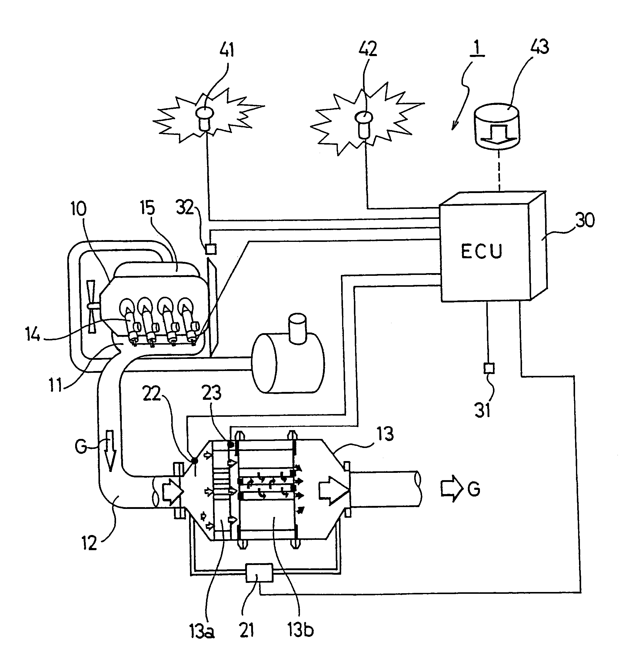
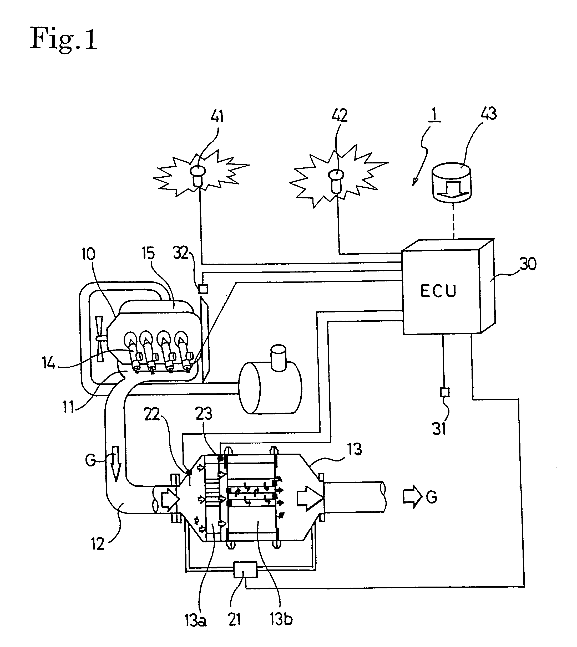
[0043]Hereinafter, the preferred embodiments of the control method for an exhaust gas purification system and the exhaust gas purification system according to the present invention will be described with reference to the accompanying drawings. The following explanation will use the example of an exhaust gas purification system provided with a continuous regeneration type diesel particulate filter (DPF) device comprising a combination of an oxidation catalyst and a filter with a catalyst.

[0044]FIG. 1 shows the configuration of an exhaust gas purification system 1 for an internal combustion engine according to an embodiment of the present invention. This exhaust gas purification system 1 is configured to provide a continuous regeneration DPF device 13 on an exhaust passage 12 connected to an exhaust manifold 11 of a diesel engine 10. This continuous regeneration DPF device 13 is configured with an oxidation catalyst 13a on the upstream side thereof and a filter with catalyst 13b on th...


PUM

PropertyMeasurementUnit
temperatureaaaaaaaaaa

Abstract

In an exhaust gas purification system with a continuous regeneration type DPF device, when a collecting quantity (ΔPm) of PM exceeds a predetermined judgment collecting quantity (ΔPm0), a number-of-regeneration-times coefficient (Rc) serving as an index of the number of regeneration times to a travel distance is compared with a predetermined judgment coefficient value (R0). When the number-of-regeneration-times coefficient (Rc) is smaller than the predetermined judgment coefficient value (R0), automatic traveling regeneration is performed. If this condition is not met, manual regeneration is performed.

Description

BACKGROUND OF THE INVENTION[0001]The present invention relates to an exhaust gas purification system that purifies particulate matters from the exhaust gas discharged by diesel and other internal combustion engines using a continuous regeneration type diesel particulate filter device and also to a control method thereof[0002]In the same way as for NOx, CO, and also HC etc., restrictions on the volume of particulate matters (hereinafter referred to as “PM”) discharged from diesel internal combustion engines grow severe every year. Techniques for collecting this PM in a filter known as a diesel particulate filter (hereinafter referred to as “DPF”) and for reducing the quantity thereof by discharging externally have been developed.[0003]DPFs for collecting this PM include a monolithic honeycomb form wall flow type filter made of ceramic, a fiber form type filter made of fiber shape ceramic or metal, and so on. An exhaust gas purification system using these DPFs are installed on the way...

Claims


Application Information

Patent Timeline
Patent Type & Authority Patents(United States)
IPC IPC(8): F01N3/00B01D46/42F02D45/00B01D53/94F01N3/02F01N3/023F01N3/18F02D41/02F02D41/38F02D41/40
CPCF01N3/0231F02D41/029F02D41/405F02D41/021Y02T10/44F02D2041/228F02D2200/0812F02D2250/11Y02T10/40
Inventor ABE, KOUZO
Owner ISUZU MOTORS LTD
Learn More