
Device for non-contacting transmission of electrical signals between two relatively moving parts, with reduced perturbing radiation

a technology of electrical signals and devices, applied in the field of devices for non-contact transmission of electrical signals, can solve problems such as electromagnetic perturbing radiation, and achieve the effect of reducing electromagnetic perturbing radiation

Inactive Publication Date: 2008-09-02
SIEMENS HEALTHCARE GMBH
View PDF11 Cites 16 Cited by
  • Summary
  • Abstract
  • Description
  • Claims
  • Application Information

AI Technical Summary

Benefits of technology

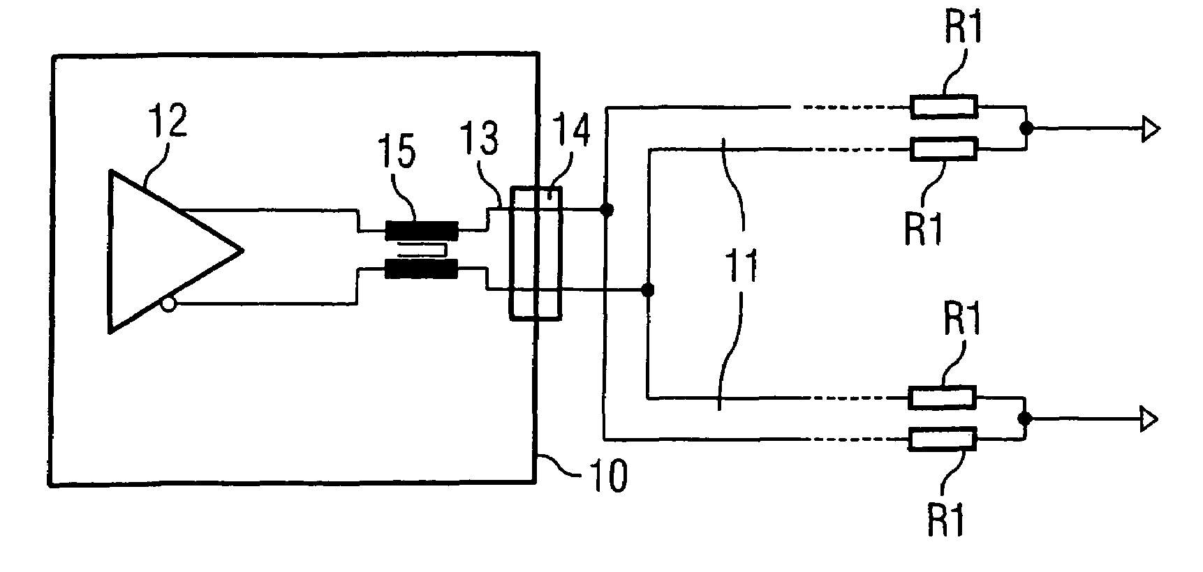
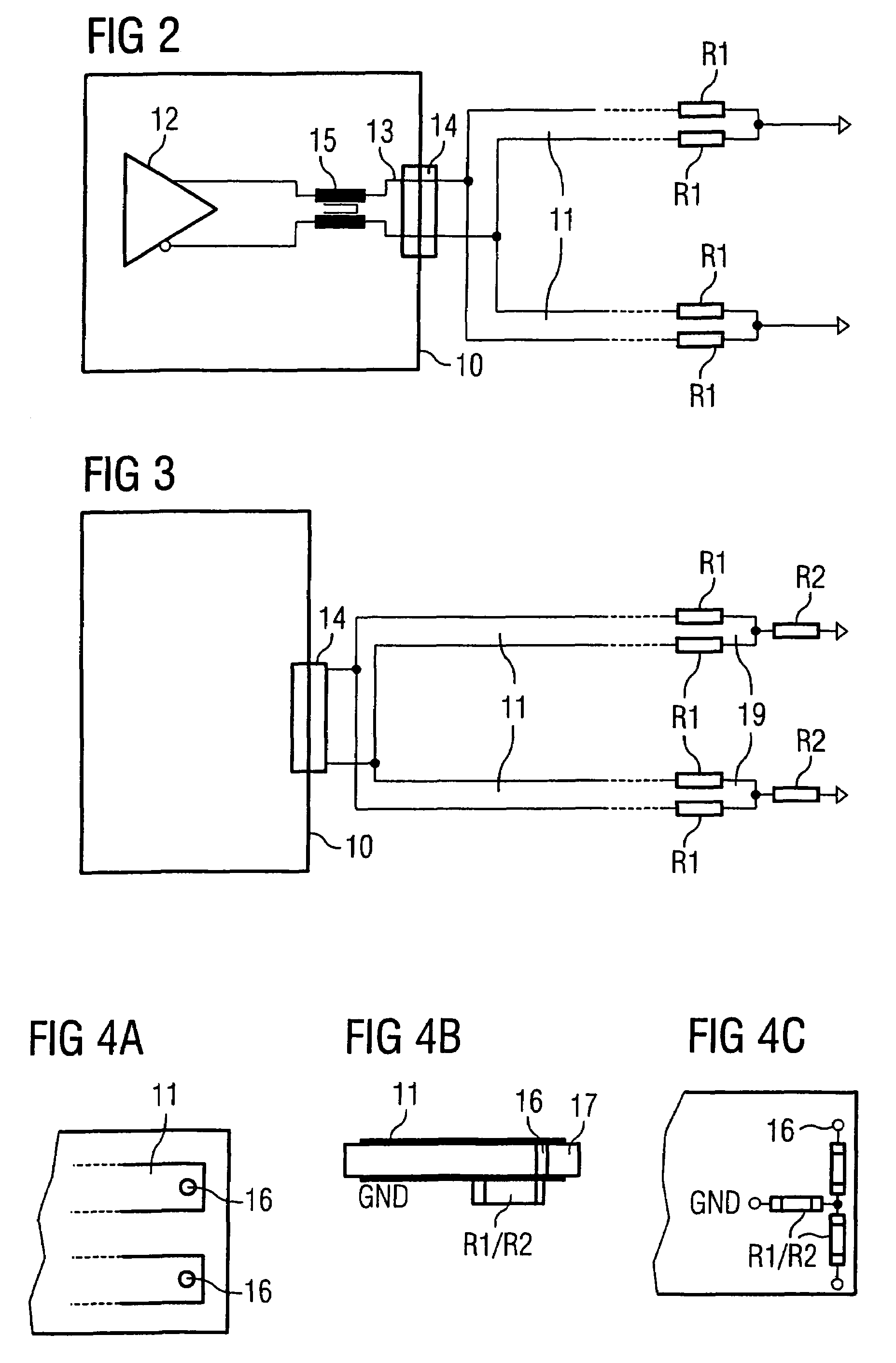
The present invention provides a device for non-contacting transmission of electrical signals between two parts moving relative to each other that reduces electromagnetic perturbing radiation. The device includes a strip conductor pair for symmetrical signal transmission and a reception element that is in communication with the conductor pair. The conductor pair is attached on the first part and the reception element is attached on the second part. The device also includes one or more components to reduce the common mode signal component, such as termination resistors, common mode chokes, and ferrite elements. The device minimizes the common mode signal component by reducing the parasitic common mode signal component and compensation elements in the transmission module. The technical effect of the invention is to reduce electromagnetic perturbing radiation during differential signal transmission.

Problems solved by technology

Even very small unwanted asymmetries in the differential signal transmission lead to standing common mode waves in the strip conductor pair that cause electromagnetic perturbing radiation.

Method used


Image

  • Device for non-contacting transmission of electrical signals between two relatively moving parts, with reduced perturbing radiation
  • Device for non-contacting transmission of electrical signals between two relatively moving parts, with reduced perturbing radiation
  • Device for non-contacting transmission of electrical signals between two relatively moving parts, with reduced perturbing radiation

Examples


Embodiment Construction

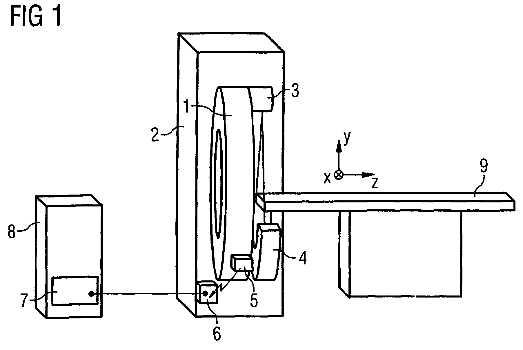
[0037]In schematized representation, FIG. 1 shows a computed tomography apparatus with a signal transmission device for transmission of measurement data from the rotating part 1 to the stationary part 2 of the gantry. Among other things, the computed tomography apparatus has an x-ray tube 3, x-ray detectors 4 arranged linearly, and a patient positioning table 9. The x-ray tube 3 and the x-ray detectors 4 are arranged at the rotating part 1 of the gantry, which rotates around the patient positioning table 9 or an examination axis Z running parallel thereto. The patient positioning table 9 normally can be displaced relative to the gantry along the examination axis Z. The x-ray tube 3 emits an x-ray beam spreading in a fan shape in a slice plane perpendicular to the examination axis Z. The x-ray beam penetrates a slice of a subject (for example a body slice of a patient who is positioned on the patient positioning table 9 in examinations) and strikes the x-ray detectors 4 situated oppo...


PUM


Abstract

A device for non-contacting transmission of electrical signals between one part moving relative to another part has at least one strip conductor pair for symmetrical signal transmission attached on a first of the two parts, in which strip conductor pair the electrical signals are supplied from a transmission module for differential signal transmission. At least one reception element is attached on the other of the two parts, at a slight separation along at least one segment of the strip conductor pair, and is connected with a reception module. The strip conductor pair is provided with one or more components for reduction of a common mode signal component that arises therein due to the differential signals therein. Additionally or alternatively, compensation elements for adaptation of a time offset between signals on the output conductors are arranged in the output conductors of the transmission module that minimizes the common mode signal component. A reduced electromagnetic perturbing radiation is achieved with the device during the non-contacting signal transmission by capacitive RF coupling.

Description

CROSS-REFERENCE TO RELATED APPLICATION[0001]The present application claims the benefit of U.S. Provisional Application No. 60 / 704,087, filed Jul. 29, 2005, which is hereby incorporated herein by reference.BACKGROUND OF THE INVENTION[0002]1. Field of the Invention[0003]The present invention concerns a device for non-contacting transmission of electrical signals between a part moving relative to another part, of the type wherein at least one strip conductor pair for symmetrical signal transmission is applied on a first of the two parts (in which strip conductor pair the electrical signals are fed from a transmission module for differential signal transmission) and in which at least one reception element is attached on a second of the two parts, the reception element moving during the relative movement of the two parts at a slight separation along at least one segment of the strip conductor pair, and being connected with a reception module. Such a device is suitable for the non-contact...

Claims


Application Information

Patent Timeline
Patent Type & Authority Patents(United States)
IPC IPC(8): H05G1/08
CPCA61B6/035A61B6/56H04L25/085H04B15/04H01P1/066
Inventor POPESCU, STEFANLEONE, MARCO
Owner SIEMENS HEALTHCARE GMBH
Learn More