
Pulsed cascaded Raman laser

a laser and cascade technology, applied in the field of lasers, can solve the problems of reducing the conversion efficiency with the increasing number, limiting the choice of longer wavelength light sources, and limited to a very low output power and/or operation at cryogenic temperatures

Inactive Publication Date: 2008-09-02
CORNING INC
View PDF7 Cites 24 Cited by
  • Summary
  • Abstract
  • Description
  • Claims
  • Application Information

AI Technical Summary

Benefits of technology

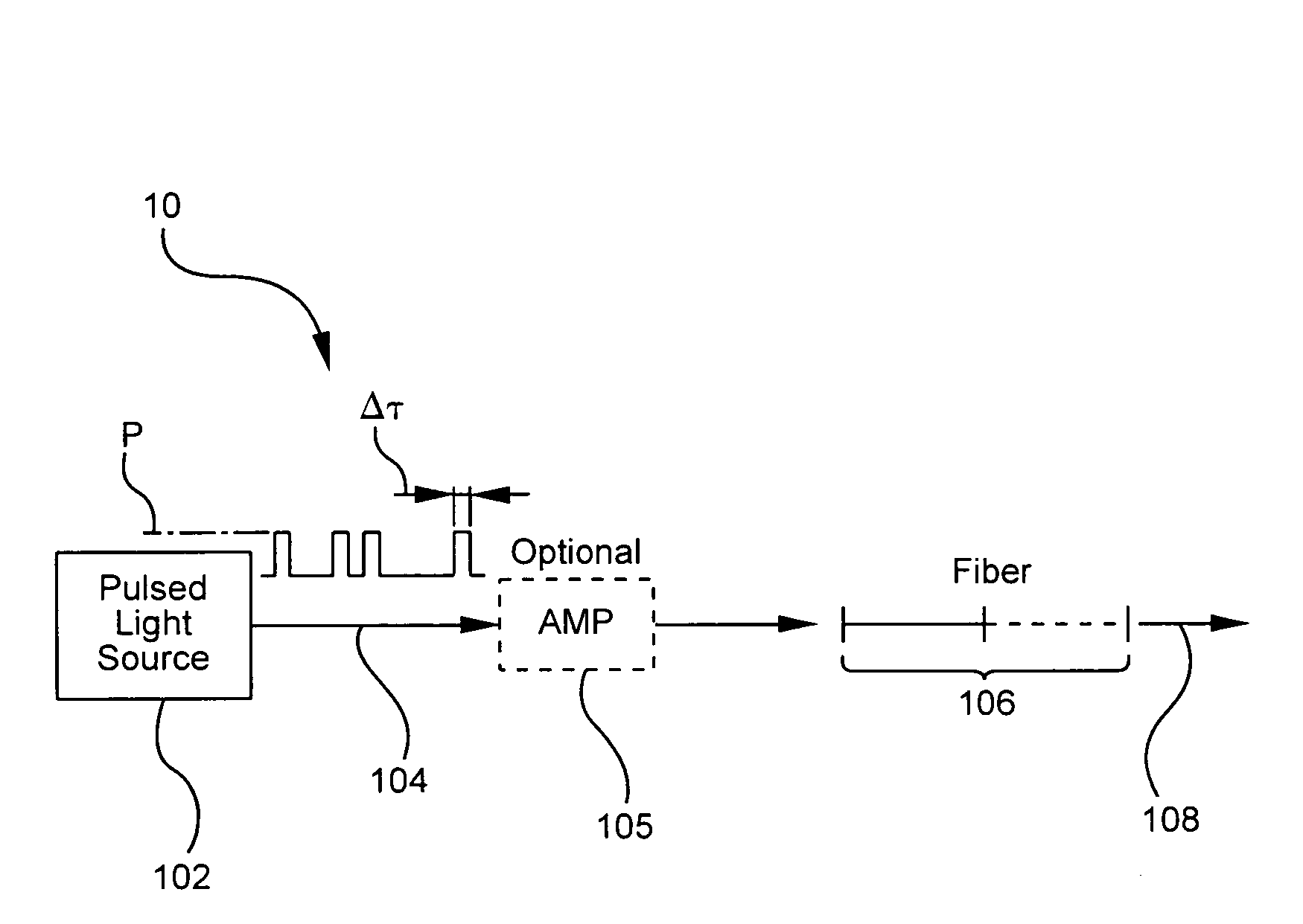
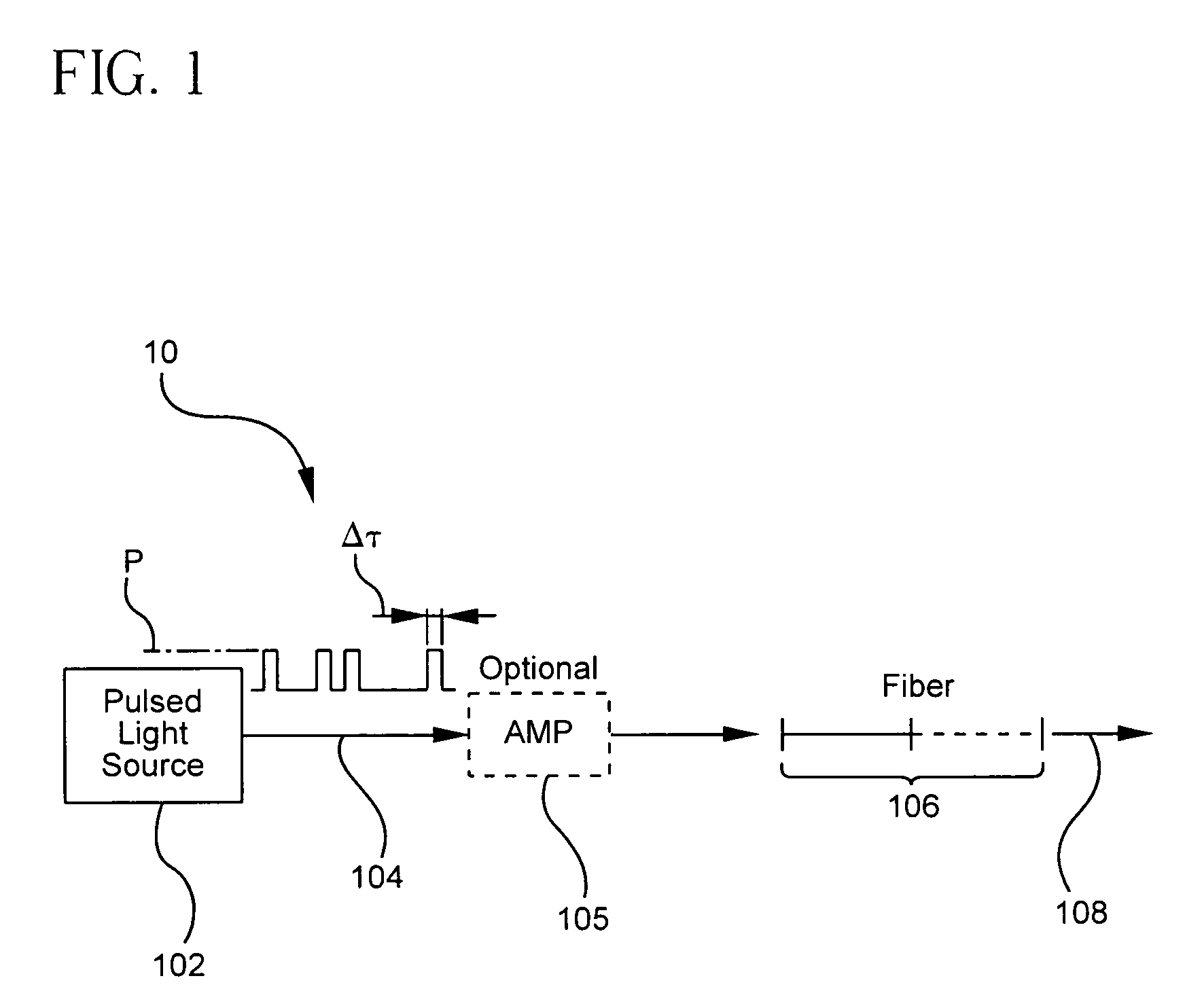
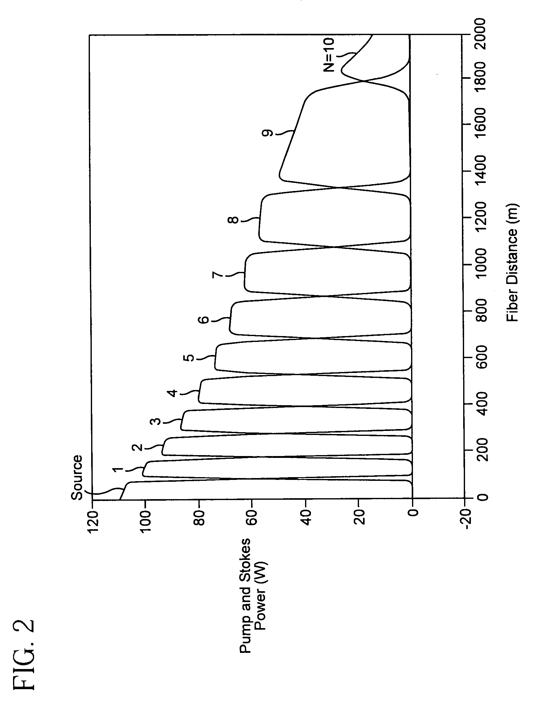
The invention is a pulsed cascaded Raman laser that converts pulsed light into a longer wavelength output using a non-linear Raman conversion fiber. The fiber is made up of different segments, each designed to convert a specific order of light. The length of each segment is determined based on the peak power and Raman gain of the first order of light and the stimulated Raman scattering threshold of the last order. The technical effect of this design is that most of the source power is converted to the desired output order in a single pass through the fiber, resulting in higher efficiency and more efficient use of the laser's power.

Problems solved by technology

However, in contrast to the widely available light sources developed for the visible and near-IR spectral ranges, the choice of the longer wavelength light sources is very limited.
InSb / InGaAsSb based and lead salt semiconductor lasers, as well as recently developed quantum cascade lasers, can operate in the mid-IR wavelength range but are limited to a very low output power and / or operation at cryogenic temperatures.
However, the main drawback of known continuous wave (CW) Raman wavelength converters is the requirement to have a pair of high reflectivity mirrors (usually fiber Bragg gratings) defining a high quality optical cavity for each intermediate Stokes component, and associated decrease in a conversion efficiency with the increasing number of SRS cascades (Stokes orders).
Although multiple hundred watt fiber lasers have recently become available, it might be difficult in practice to propagate that much power in a nonlinear fiber (with large enough Raman gain) and avoid stimulated Brillouin scattering in a backward direction.

Method used


Image

  • Pulsed cascaded Raman laser
  • Pulsed cascaded Raman laser
  • Pulsed cascaded Raman laser

Examples


Embodiment Construction

[0018]A non-cavity or non-resonant method and apparatus for generating coherent light are taught herein. In accordance with the teachings of the present invention, cascaded stimulated Raman scattering (SRS) of pulsed pump radiation in an optical fiber with normal (negative) dispersion is used in the inventive method and apparatus to result in multiple order wavelength shifts of initially shorter wavelength towards longer wavelengths.

[0019]Reference will now be made in detail to the present preferred embodiments of the invention, examples of which are illustrated in the accompanying drawings. Whenever possible, the same reference numerals will be used throughout the drawings to refer to the same or like parts. One embodiment of the wavelength converter or Raman laser of the present invention is shown in FIG. 1, and is designated generally throughout by the reference numeral 10.

[0020]Referring to FIG. 1, a pulsed cascaded Raman laser 10 includes a pulsed light source 102 for generatin...


PUM


Abstract

A pulsed cascaded Raman laser (10) includes a pulsed light source (102) for generating a pulsed light (104) having an optical spectrum centered at a source wavelength. A non-linear Raman conversion fiber (106) is coupled to the pulsed light source (102). The pulsed light (104) traverses the nonlinear Raman conversion fiber (106) and the source power at the source wavelength is converted to a power output of an output signal (108) having an output wavelength longer than the source wavelength by a cascaded Stimulated Raman Scattering process, such that most of the source power is converted to the power of the last Stokes order in a single pass through the non-linear Raman conversion fiber (106).

Description

BACKGROUND OF THE INVENTION[0001]1. Field of the Invention[0002]The present invention relates generally to Raman lasers, and particularly to pulsed cascaded Raman lasers operating at least in the mid-infrared (IR) wavelength range.[0003]2. Technical Background[0004]Coherent light sources in 1.8-2.0 μm wavelength range and beyond in the mid-IR (2-10 μm) find a number of important applications (such as medicine, life sciences, spectroscopy, and environmental sensing). Important applications also exist for even higher wavelength ranges past the end of the theoretical mid-IR wavelength of 10 μm. However, in contrast to the widely available light sources developed for the visible and near-IR spectral ranges, the choice of the longer wavelength light sources is very limited. InGaAsP / InP based semiconductor lasers, both edge-emitting and vertical-cavity surface emitting (VCSEL) lasers are limited to the operational wavelength shorter than 1.8 μm. InSb / InGaAsSb based and lead salt semicondu...

Claims


Application Information

Patent Timeline
Patent Type & Authority Patents(United States)
IPC IPC(8): H01S3/30
CPCH01S3/302H01S3/08086H01S3/094003H01S3/1675H01S3/177H01S3/1631
Inventor KOROLEV, ANDREYKUKSENKOV, DMITRI V.NAZAROV, VLADIMIR
Owner CORNING INC
Learn More