Method for determining optimum grating parameters for producing a diffraction grating for a VUV spectrometer

a diffraction grating and optimal grating technology, applied in the direction of optical radiation measurement, instruments, spectrometry/spectrophotometry/monochromators, etc., can solve the problems of loss of resolution, reduced spectrometer efficiency, and inability to produce sharp images

Inactive Publication Date: 2008-09-02
FORSCHUNGSZENTRUM JULICH GMBH
View PDF3 Cites 4 Cited by
  • Summary
  • Abstract
  • Description
  • Claims
  • Application Information

AI Technical Summary

Benefits of technology

[0082]F.5) Step F.4 allows an exact determination of the position of the detector in a simple way (from a linear equation)

Problems solved by technology

As a result there is a loss of resolution and a reduction in the efficiency of the spectrometer.
The use of planar detectors however resulted in images which were not sharp.
In addition, significant light losses arose (typically by a factor of 2 to 10) as a result of astigmatism in the imaging.
Engraved gratings had in addition a high level of light scattering because the grating lines were not perfectly uniform.
This technique however in spite of the high cost was unable to solv

Method used


Image

  • Method for determining optimum grating parameters for producing a diffraction grating for a VUV spectrometer
  • Method for determining optimum grating parameters for producing a diffraction grating for a VUV spectrometer
  • Method for determining optimum grating parameters for producing a diffraction grating for a VUV spectrometer

Examples


Embodiment Construction

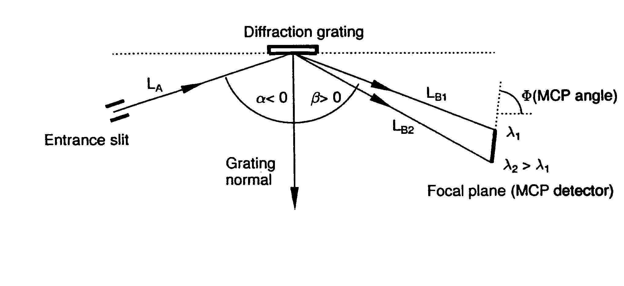
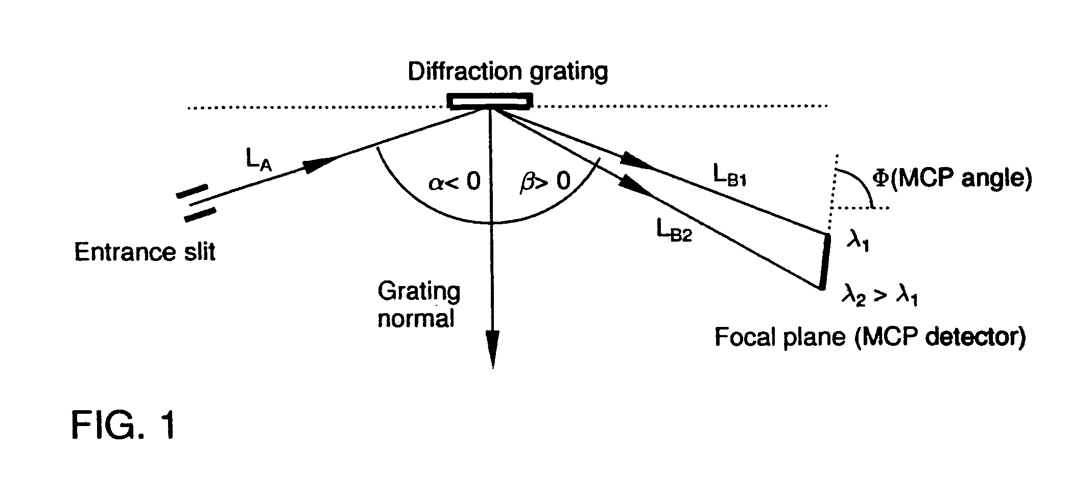
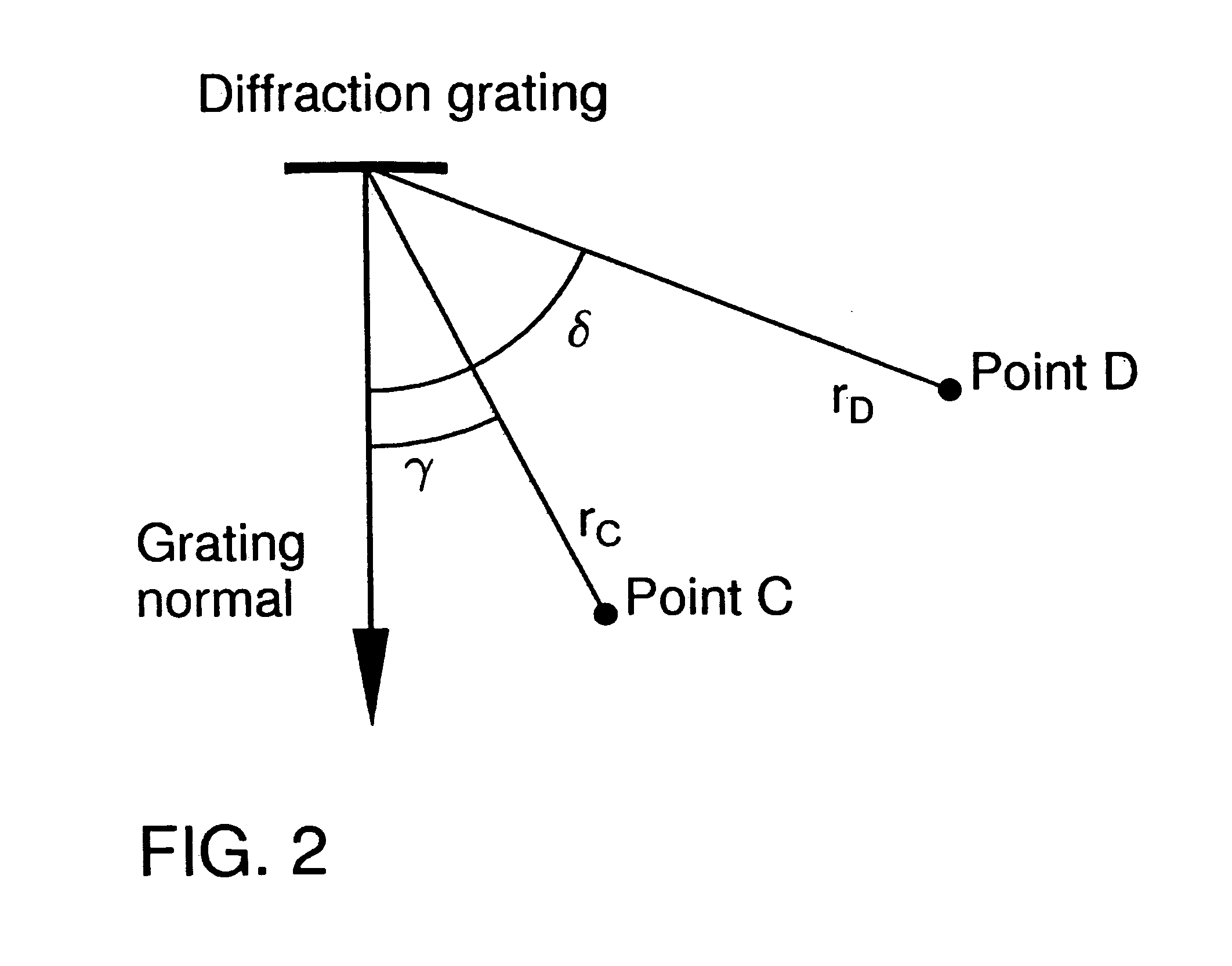
[0102]Below the results of four grating designs have been set forth. The following definitions apply:[0103]A. Holographic grating parameter:[0104]R: Greater radius of the toroidal grating substrate[0105]ρ: Smaller radius of the toroidal grating substrate[0106]rc, rd: Spacing of the holographic illumination or exposure points from the grating origin[0107]γ, δ: Angular position or setting of the holographic illumination or exposure points to the grating normal[0108]λ: Laser wavelength[0109]B: Spectrometer parameters[0110]LA: Inlet gap / grating center point spacing,[0111]rso: Spacing from grating origin to meridional focus of zero order[0112]LB: Spacing of grating center point to detector,[0113]α: Incident angle of the radiation to the grating normal,[0114]β: Emergent angle of the beam to the grating normal,[0115]λ: Wavelength of the radiation within a previously defined wavelength range line density at the grating origin,[0116]MCP angle: Setting angle of detector relative to grating ta...


PUM


Abstract

A method for determining a set of grating parameters for producing a diffraction grating for a vacuum-ultraviolet spectrometer, the parameters used being the small and large radius of the toroidal grating substrate, the two distances between the two holographic illumination points and the grating origin, the angular position of the holographic illumination points in relation to the grating normal, and the laser wavelength for the holographic illumination. The method determines respective optimum grating parameters on numeric iterative paths for a specific problem definition. The method thus advantageously enables the production of a VUV spectrometer having a diffraction grating that for a predetermined wavelength range produces a minimum line width on the detector with a large range.

Description

CROSS REFERENCE TO RELATED APPLICATIONS[0001]This application is the US national phase of PCT application PCT / DE2004 / 000058 filed 17 Jan. 2004 with a claim to the priority of German patent application 10307884.3 itself filed 25 Feb. 2003.FIELD OF THE INVENTION[0002]The invention relates to a method of determining optimal grating parameters for a holographic diffraction grating, especially for a diffraction grating for a VUV spectrometer with a planar detector.STATE OF THE ART1. VUV-Spectrometer and Grating Technology[0003]All elements and their (incompletely ionized) ions can be singularly identified based upon their characteristic line emissions or radiation and so distinguished from one another. For the measurement of this radiation today one usually utilizes a spectrometer which spectrally breaks up the radiation of a diffraction grating and detects the spectra thus formed with a detector in terms of the intensity as a function of wavelength.[0004]The most intensive resonance lin...

Claims


Application Information

Patent Timeline
IPC IPC(8): G02B5/18G01J3/18
CPCG02B5/1857G01J3/18Y10S359/90
Inventor BIEL, WOLFGANG
Owner FORSCHUNGSZENTRUM JULICH GMBH
Why Eureka
Try Eureka