
Radiation image detection method and system

a radiation image and detection method technology, applied in the direction of instruments, patient positioning for diagnostics, applications, etc., can solve the problems of deteriorating image quality of radiation image, thick thickness of radiation image detector, etc., to improve the image quality of readout radiation image, reduce the cost, and efficiently erase the remaining electric charge

Inactive Publication Date: 2008-09-02
FUJIFILM CORP +1
View PDF4 Cites 8 Cited by
  • Summary
  • Abstract
  • Description
  • Claims
  • Application Information

AI Technical Summary

Benefits of technology

The present invention provides a radiation image detection method and system that use an up-conversion phosphor layer to improve image quality by erasing remaining electric charge trapped in the first electrode layer. The method involves irradiating the up-conversion phosphor layer with infrared light from the second electrode layer side, resulting in the emission of fluorescence. The system includes a radiation image detector with an up-conversion phosphor layer, a first electrode layer, a photoconductive layer for recording, a charge storage portion, a photoconductive layer for readout, and a second electrode layer. The method and system can improve image quality by reducing blurring and increasing the sharpness of the radiation image.

Problems solved by technology

Therefore, when a next radiation image is recorded, there is a risk that the image quality of the radiation image deteriorates because the next radiation image is recorded without erasing the electric charge remaining in the vicinity of the first electrode.
However, there is a problem that if a light source unit for erasing light is provided on the first electric side, the thickness of the radiation image detector becomes thick.

Method used


Image

  • Radiation image detection method and system
  • Radiation image detection method and system
  • Radiation image detection method and system

Examples


Embodiment Construction

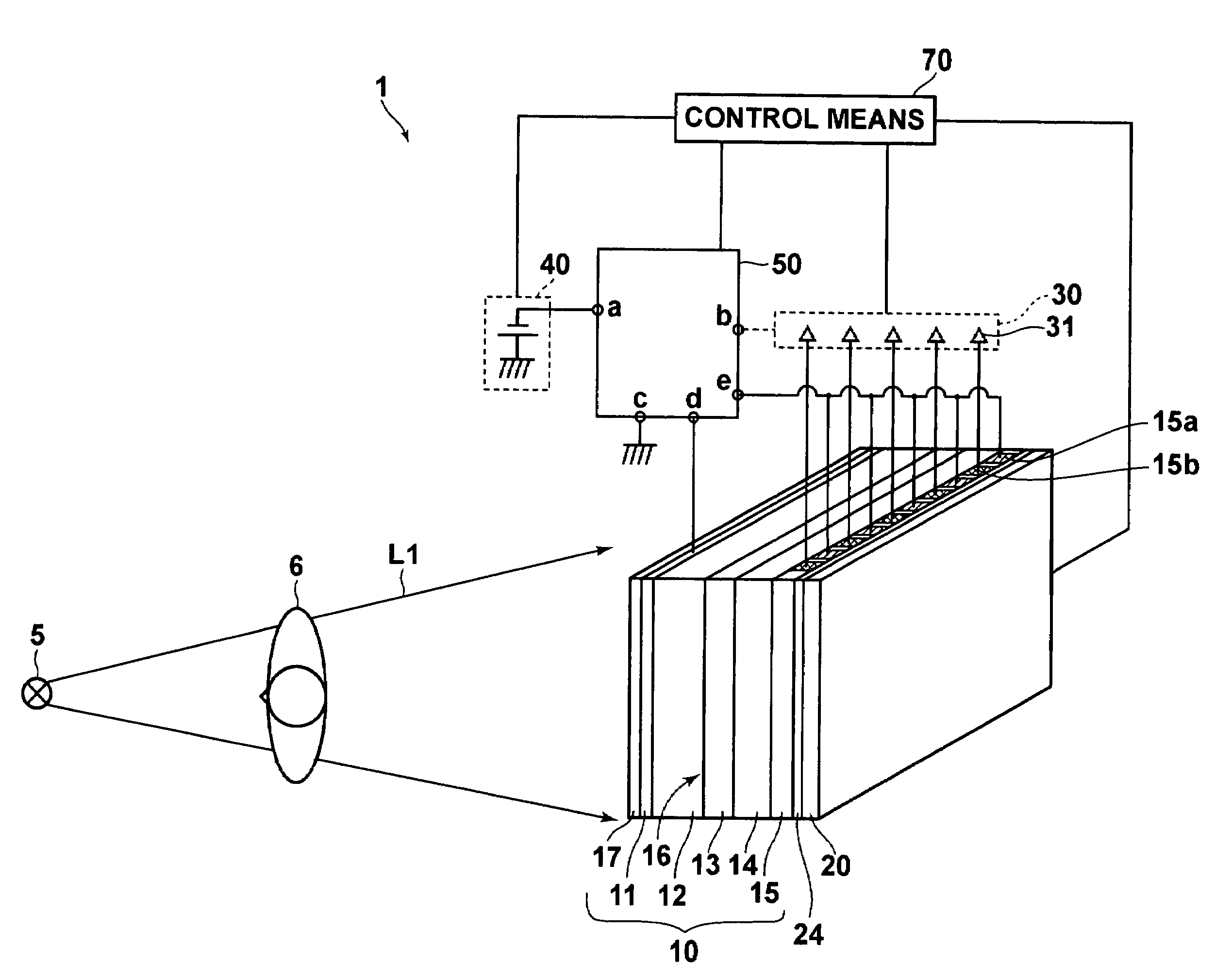
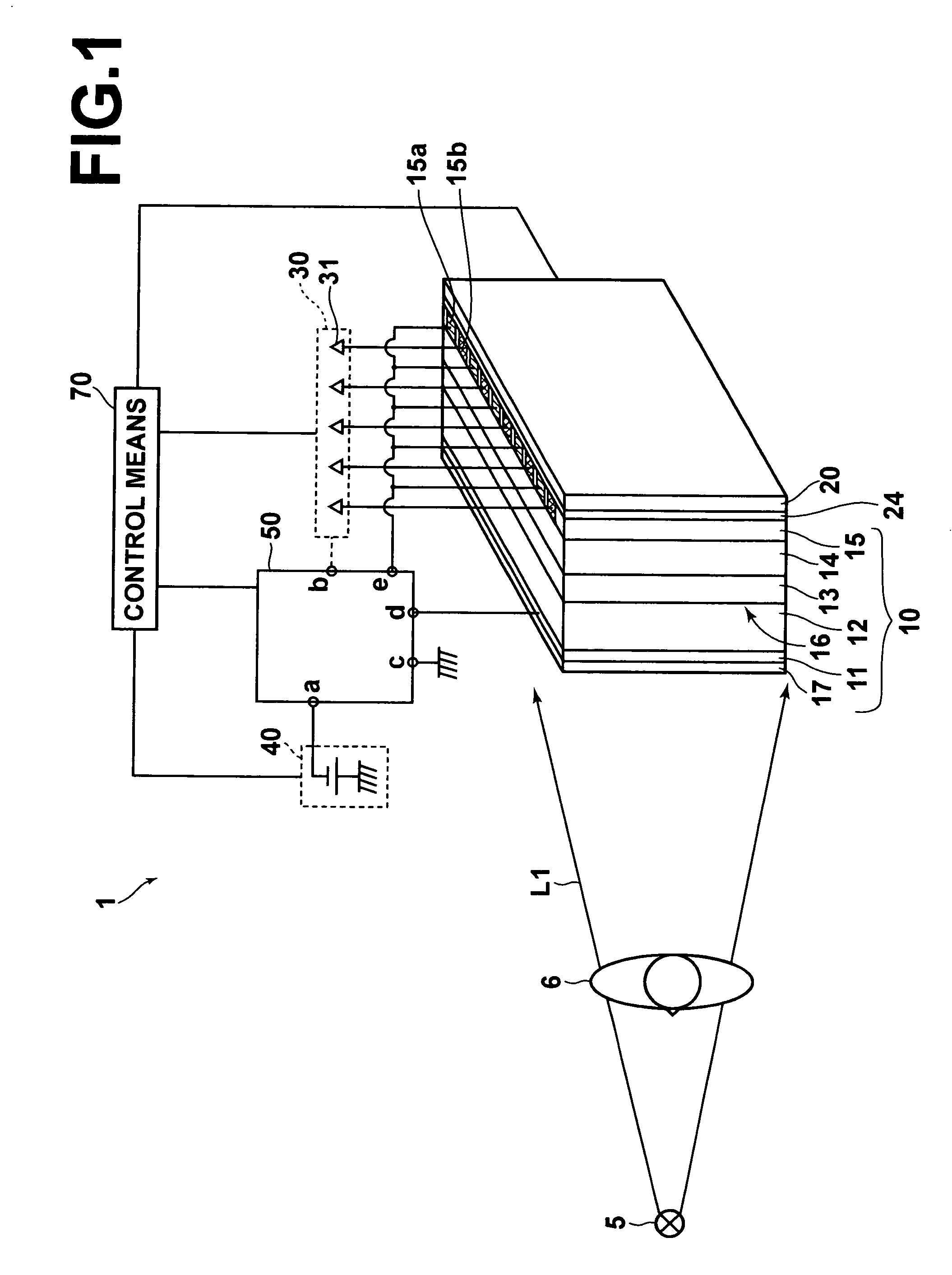
[0035]Hereinafter, embodiments of a radiation image detection method and a radiation image detection system according to the present invention will be described with reference to attached drawings. FIG. 1 is a schematic diagram illustrating the configuration of a radiation image recording / readout apparatus 1, which is an embodiment of the present invention.

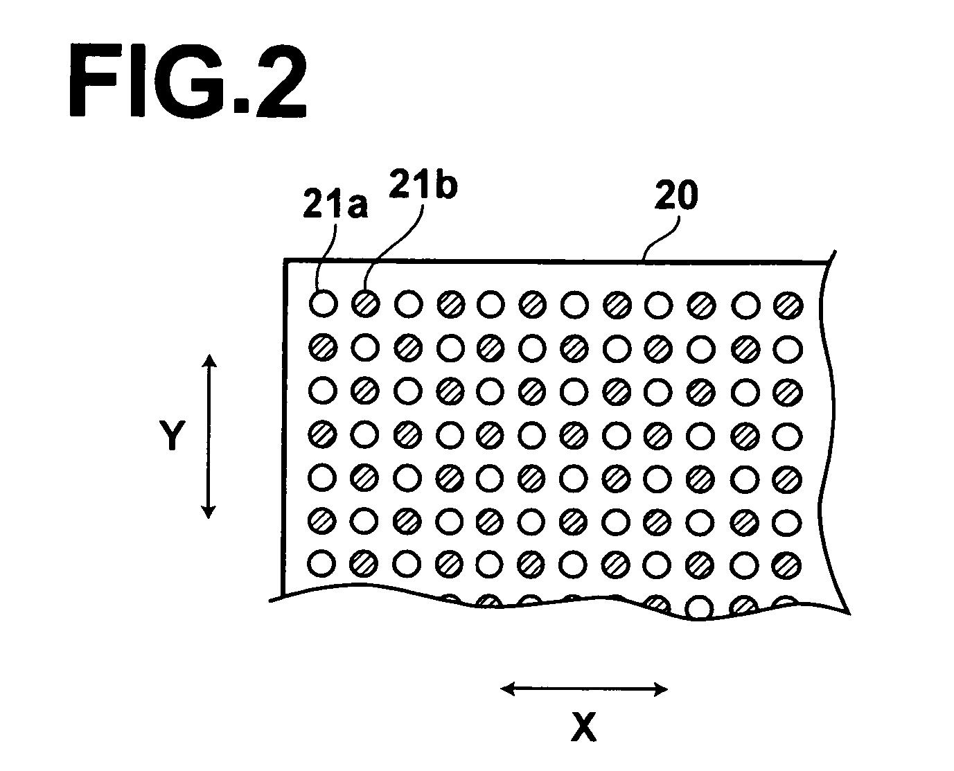
[0036]A radiation image recording / readout apparatus 1 according to the present invention includes a radiation source 5, a radiation image detector 10, a plane-shaped light source 20, an electric current detection unit 30, a voltage source 40, a switch means 50 and a control means 70, as illustrated in FIG. 1. The radiation source 5 emits radiation L1. The radiation image detector 10 detects a radiation image of a subject 6 by irradiation with the radiation L1 which has been emitted from the radiation source 5 and transmitted through the subject 6. The plane-shaped light source 20 emits blue light L2 and infrared light L3 to the ra...


PUM


Abstract

A radiation image detector includes an up-conversion phosphor layer for emitting fluorescence by irradiation with infrared light, a first electrode layer for transmitting the infrared light, the fluorescence and radiation carrying a radiation image, a photoconductive layer for recording, a charge storage portion, a photoconductive layer for readout, and a second electrode layer for transmitting the infrared light and the readout light. Radiation is recorded as latent image charge in the charge storage portion. The electric charge is read out from the charge storage portion by irradiating the photoconductive layer for readout with the readout light from the second electrode layer side. The up-conversion phosphor layer is irradiated with the infrared light from the second electrode layer side and remaining charge in the vicinity of the first electrode layer is erased by fluorescence emitted from the up-conversion phosphor layer by irradiation with the infrared light.

Description

BACKGROUND OF THE INVENTION[0001]1. Field of the Invention[0002]The present invention relates to a radiation image detection method and a radiation image detection system for reading out a radiation image recorded in a radiation image detector by irradiating the radiation image detector with readout light. The radiation image recorded in the radiation image detector is an image recorded by storing electric charge, based on the dose of radiation, generated by irradiation with radiation carrying a radiation image.[0003]2. Description of the Related Art[0004]Conventionally, a radiation image detection system which records radiation images using a radiation image detector, and which reads out the radiation images recorded in the radiation image detector as electric signals has been widely utilized in medical radiography or the like. Further, various kinds of such radiation image detection system have been proposed. In the radiation image detector, a radiation image of a subject is detec...

Claims


Application Information

Patent Timeline
Patent Type & Authority Patents(United States)
IPC IPC(8): G01T1/16
CPCB82Y10/00G21K4/00G21K2201/061G21K2004/06G21K2004/04
Inventor IRISAWA, KAKU
Owner FUJIFILM CORP
Learn More