
SISO decoder

a decoder and data technology, applied in the direction of coding, code conversion, electrical apparatus, etc., can solve the problems of less certainty, less distinguishing between digital signals, flowing digital signals with substantial volume, etc., to improve memory and processing capacity, improve resolution, and improve the effect of memory and processing capacity

Active Publication Date: 2008-08-19
COMTECH EF DATA
View PDF2 Cites 12 Cited by
  • Summary
  • Abstract
  • Description
  • Claims
  • Application Information

AI Technical Summary

Benefits of technology

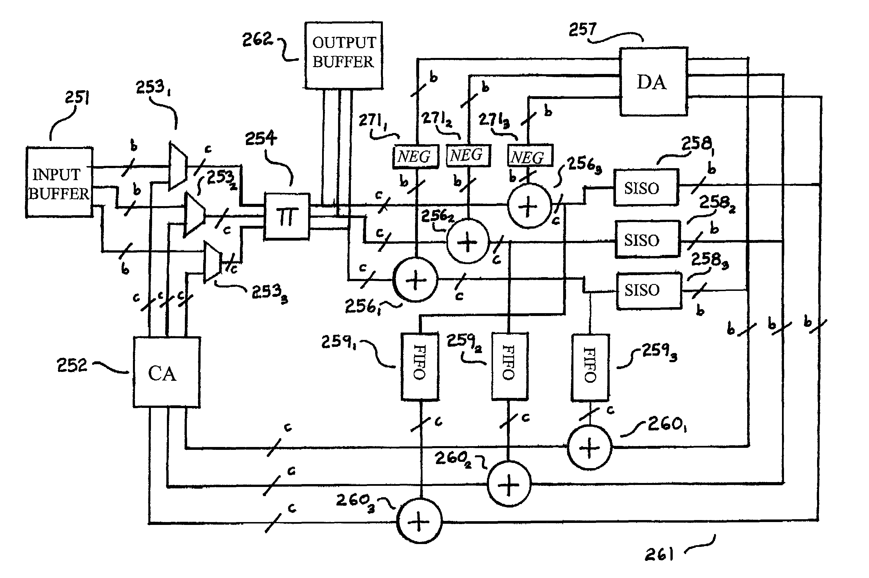
"The present invention is a new method for decoding data using a parallel SISO structure that allows the decoder to process multiple parity equations at the same time. The invention includes a mapping structure that correctly aligns the stored estimates to the stored differences for presentation to the SISO's. The invention also manages the updates and the differences in such a manner that all calculations on a single piece of data that are processed in parallel are incorpor correctly in the new updated estimates. The LDPC architecture of the present invention makes better use of memory and processing capacity during decoding, requires the same number of memory locations as the slow architecture of Richardson, and requires only the small memory as the higher resolution. Another significant difference between the present invention and the Richardson architectures is how permutations are handled. The present invention stores all the variable messages in their unpermuted form and the check messages in their permuted form, which requires a permutation block for each memory access. The architecture of the present invention represents the differences in their permuted form, and the variable nodes are stored in the same permutation as the last time they were accessed. This is a significant savings, as the permutation is a fairly large function."

Problems solved by technology

Although the difference between the two binary values, zero and one, seems clear, like the difference between black and white, in practice an electronic device may have difficulty distinguishing the difference.
The difference between binary values may be detected as a voltage difference, but electronic noise in a circuit can interfere and render the difference less certain.
However, this is impossible with some fast flowing digital signals with substantial volume, such as digital TV, and is impractical in many situations.
Retransmission may increase the reliability of the data being transmitted or stored, but such a system demands more transmission time or bandwidth or memory, and in some applications, such as digital TV signals, it may be impossible with current technology.

Method used


Image

  • SISO decoder
  • SISO decoder
  • SISO decoder

Examples


Embodiment Construction

1. The Coding Process

[0032]Communication systems often use forward error correction to correct errors induced by noise in a transmission channel. In such forward error correction systems, the detection and correction of errors occur at the receiver. Bits received through the channel are detected at the receiver as “soft” values. A soft value represents the “best guess” that the receiver can make for the value of the bit that was sent and the confidence in that guess. In essence, data is sent as a single bit, and received as a multi-bit sample. During transmission, a single bit of data may pick up noise, so that it is necessary to use more than a single bit to identify the sampled data. For example, in a binary system, if a “1” is coded as 5 volts and a “0” as 0 volts, then each can be represented with a single bit. If a value of 4.2 volts is received, then this is close to representing a “1”, but the receiver will use multiple bits to represent how close to the 5 volts the sampled d...


PUM


Abstract

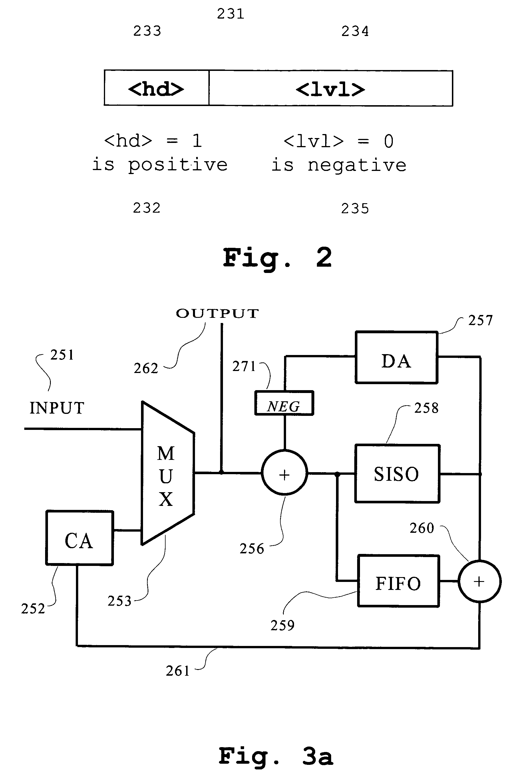
The current invention involves a forward error detection system, especially for use with Low Density Parity Check codes. A parallel SISO structure allows the decoder to process multiple parity equations at the same time. There is a new SISO decoder which allows for the updating of the Log-likelihood-ratio's in a single operation, as opposed to the two pass traditionally associated with the Tanner Graph's. In the decoder, there is a mapping structure that correctly aligns the stored estimates, the stored differences and the SISO's. There is also the ability to deal with multiple instances of the same data being processed at the same time. This structure manages the updates and the differences in such a manner that all calculations on a single piece of data that are processed in parallel are incorporated correctly in the new updated estimates.

Description

CLAIM OF PRIORITY TO PROVISIONAL APPLICATION (35 U.S.C. § 119(e))[0001]This application claims priority under 35 U.S.C. § 119(e) from provisional patent Application No. 60 / 568,939, filed May 7, 2004. The 60 / 568,939 Application is incorporated herein by reference.FIELD OF THE INVENTION[0002]The present invention relates to error correction systems for computer data. More specifically, the invention relates to the use of parity check codes such as a low density parity check code (“LDPC”).BACKGROUND OF THE INVENTION[0003]The transmission of binary computer data involves the introduction of errors, which must be detected and corrected, if possible. Although the difference between the two binary values, zero and one, seems clear, like the difference between black and white, in practice an electronic device may have difficulty distinguishing the difference. The difference between binary values may be detected as a voltage difference, but electronic noise in a circuit can interfere and ren...

Claims


Application Information

Patent Timeline
Patent Type & Authority Patents(United States)
IPC IPC(8): H03M13/00H03M7/00H03M13/11H03M13/45
CPCH03M13/1105H03M13/1117H03M13/1122H03M13/6561H03M13/116H03M13/45H03M13/1137
Inventor BANISTER, BRIAN A.OWSLEY, PATRICK A.HANSEN, TOM
Owner COMTECH EF DATA
Learn More