Gas-insulated switchgear device
a switchgear device and gas-insulated technology, which is applied in the direction of air-break switches, non-enclosed substations, substations, etc., can solve the problems of concentrating load of branch bus lines, requiring the carrying out of circuit breakers that must be dismantled and repaired, and requiring dismantling and inspection work. , to achieve the effect of convenient carrying out and convenient carrying ou
- Summary
- Abstract
- Description
- Claims
- Application Information
AI Technical Summary
Benefits of technology
Problems solved by technology
Method used
Image
Examples
first embodiment
[0023]FIG. 2 is a single connection diagram of a gas-insulated switchgear device according to the present invention.
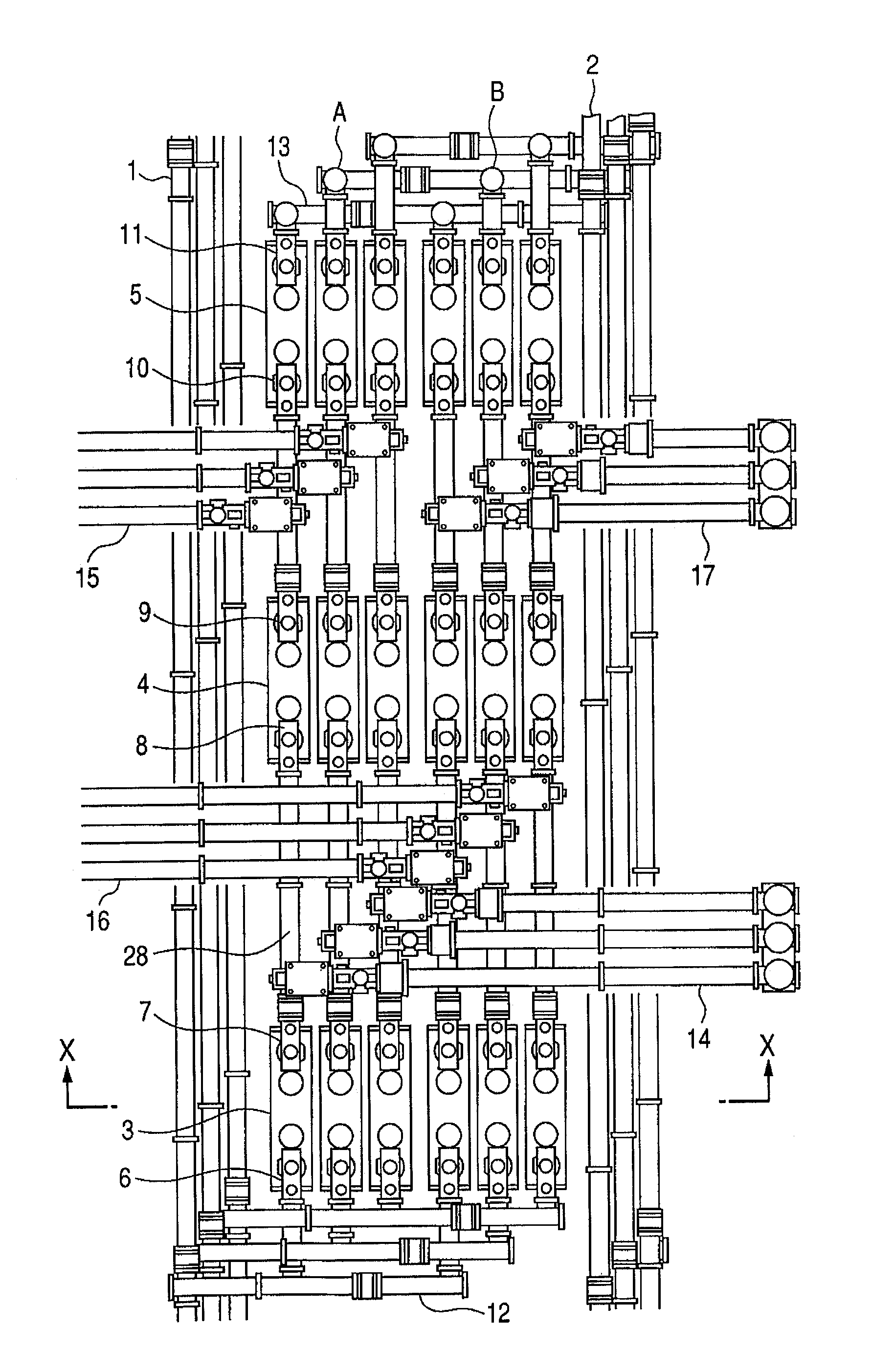
[0024]Main bus lines 1, 2 are spaced a predetermined distance apart from each other and disposed in substantially parallel to each other. In a space between these main bus lines 1, 2, two diameters A, Bare provided. The diameter A which is adjacent to the main bus line 1 is constructed by causing three circuit breakers 3, 4, 5 to be spaced a predetermined distance apart from one other and disposed on a hypothetical vertical plane which passes a center line substantially parallel to the main bus line 1. An earth switch-mounted disconnecting switch 6 which is connected to one side of the circuit breaker 3, is connected to an auxiliary bus line 12 which is disposed so as to be substantially perpendicular to the main bus lines 1, 2 and connected to the main bus line 1. An earth switch-mounted disconnecting switch 7 which is connected to the other side of the circuit breake...
second embodiment
[0048]FIG. 5 is a plan view of a gas-insulated switchgear device according to the present invention.
[0049]In this example, diameters C, D are added to the gas-insulated switchgear device of FIG. 1. In FIG. 5, elements which are equivalent to the elements of the gas-insulated switchgear device of FIG. 1 are denoted by the same reference numerals. The main bus lines 1, 2 are spaced a predetermined distance apart from each other and disposed in substantially parallel to each other. The three circuit breakers 3, 4, 5 of the diameter A partially shown in FIG. 5 are disposed along the axial directions of the main bus lines 1, 2. One ends of the three circuit breakers 3, 4, 5 are connected to the main bus line 1 through the auxiliary bus 12. Three circuit breakers 3, 4, 5 of the diameter B are juxtaposed with the three circuit breakers 3, 4, 5 of the diameter A. The branch bus line 14 interconnecting the circuit breakers 3, 4 of the diameter B is led out toward the main bus line 1 like the...
PUM
 Abstract
Description
Claims
Application Information
 - R&D
- Intellectual Property
- Life Sciences
- Materials
- Tech Scout
- Unparalleled Data Quality
- Higher Quality Content
- 60% Fewer Hallucinations
Browse by: Latest US Patents, China's latest patents, Technical Efficacy Thesaurus, Application Domain, Technology Topic, Popular Technical Reports.
© 2025 PatSnap. All rights reserved.Legal|Privacy policy|Modern Slavery Act Transparency Statement|Sitemap|About US| Contact US: help@patsnap.com


