Scattered light range of view measurement apparatus

a measurement apparatus and scattering light technology, applied in the direction of instruments, measurement devices, surveying and navigation, etc., can solve problems such as interference with the proper functioning of instruments, and achieve the effects of strong light signal, avoiding adverse interference, and increasing its effectiveness

Active Publication Date: 2008-08-19
SICK AG
View PDF5 Cites 0 Cited by
  • Summary
  • Abstract
  • Description
  • Claims
  • Application Information

AI Technical Summary

Benefits of technology

[0015]An advantage of the present invention is that with the periodically activated transmissions light path via the light deflector, a desired additional transmission measurement can be made. As compared to the scattered light measurement method, this generates a strong light signal for the light receiver, particularly when the range of sight is good. This then enables a functional testing of the scattered light measuring instrument. Since the transmissions light path uses the same light emitter and the same light receiver as is used during normal scattered light measurements, the instrument of the present invention has the significant advantage that possible component alterations or changes of the optoelectronic components have no effect.
[0016]A further advantage of the present invention is that the geometric spaces traversed by the light are the same and do not differ from each other. This has the advantage that obstacles that may be present in the light radiation space and the optical boundary surfaces are the same for both and can therefore be securely recognized. Such optical boundary surfaces are used in scattered light instruments to protect the instrument from dirt and contamination. Nevertheless, dirt and contaminants can deposit on these optical boundary surfaces, which can interfere with the proper functioning of the instrument. Through the activation of the transmissions light path in accordance with the present invention, even such contaminating deposits are recognized, which is not possible with conventional scattered light range measuring instruments. Since the transmissions light path cannot continuously be active, the present invention provides an optical shutter which temporally controls the opening and closing of the transmissions light path. For this, the present invention contemplates, for example, to interrupt the light path by operating the shutter with a rotatable magnet. It is also possible to operate the shutter with a stepping motor, a magnetic cylinder or other suitable drive units.
[0017]If it is not possible to place the optical shutter in the transmissions light path, it is advantageous to position the shutter immediately in front of, behind or within the light deflector to avoid adverse interferences from other reflections that can occur in the instrument.
[0018]In a particularly preferred embodiment, the light deflector is constructed of either a flexible or a rigid light conduit or conductor. Especially the use of a flexible light conductor is useful because the light transmissions path can then be easily conformed to the encountered geometric configuration of the instrument.
[0019]The use of a light conduit for the light deflector further increases its effectiveness because the amount of light which is relayed via the transmissions path in accordance with the present invention can be increased by placing connecting optics at the respective ends of the light conduit. The reason for this is that a convex lens positioned at the correct distance from the light conduit has an opening that is significantly larger than the cross-section of the light conduit. As a result, a greater amount of light can be fed into the light conduit. Similarly, a corresponding connector for decoupling the light conduit has the advantage that light emitted at the other end of the conduit can be angularly directed towards the light receiver so that it receives the major portion of the light emitted by the light conduit.
[0020]For controlling the operation of the optical shutter and therewith the activation of the transmissions light path, the present invention preferably uses a timed activation system. This makes it possible to automatically control the activations of the transmissions path, the temporal spacing between shutter openings, and the duration of the openings. In this manner, the operation of the scattered light instrument can be optically adapted to the encountered installation and requirements.

Problems solved by technology

In particular, such a scattered light range of view measurement instrument should generate an unequivocal indication of the degree of contamination at optical boundary surfaces.
Nevertheless, dirt and contaminants can deposit on these optical boundary surfaces, which can interfere with the proper functioning of the instrument.

Method used


Image

  • Scattered light range of view measurement apparatus
  • Scattered light range of view measurement apparatus
  • Scattered light range of view measurement apparatus

Examples


Embodiment Construction

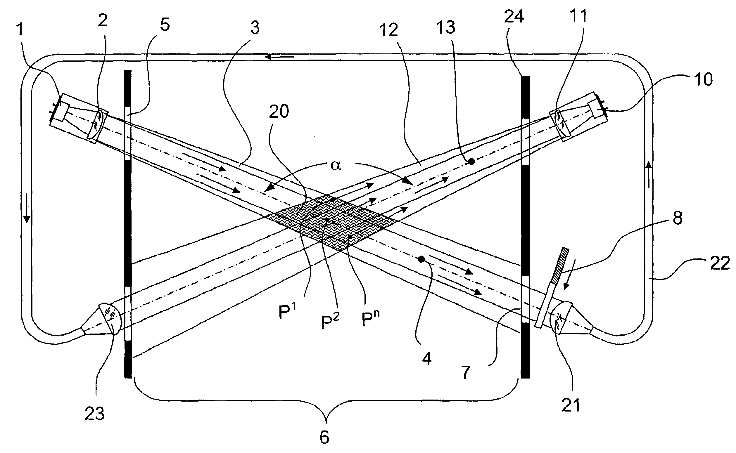
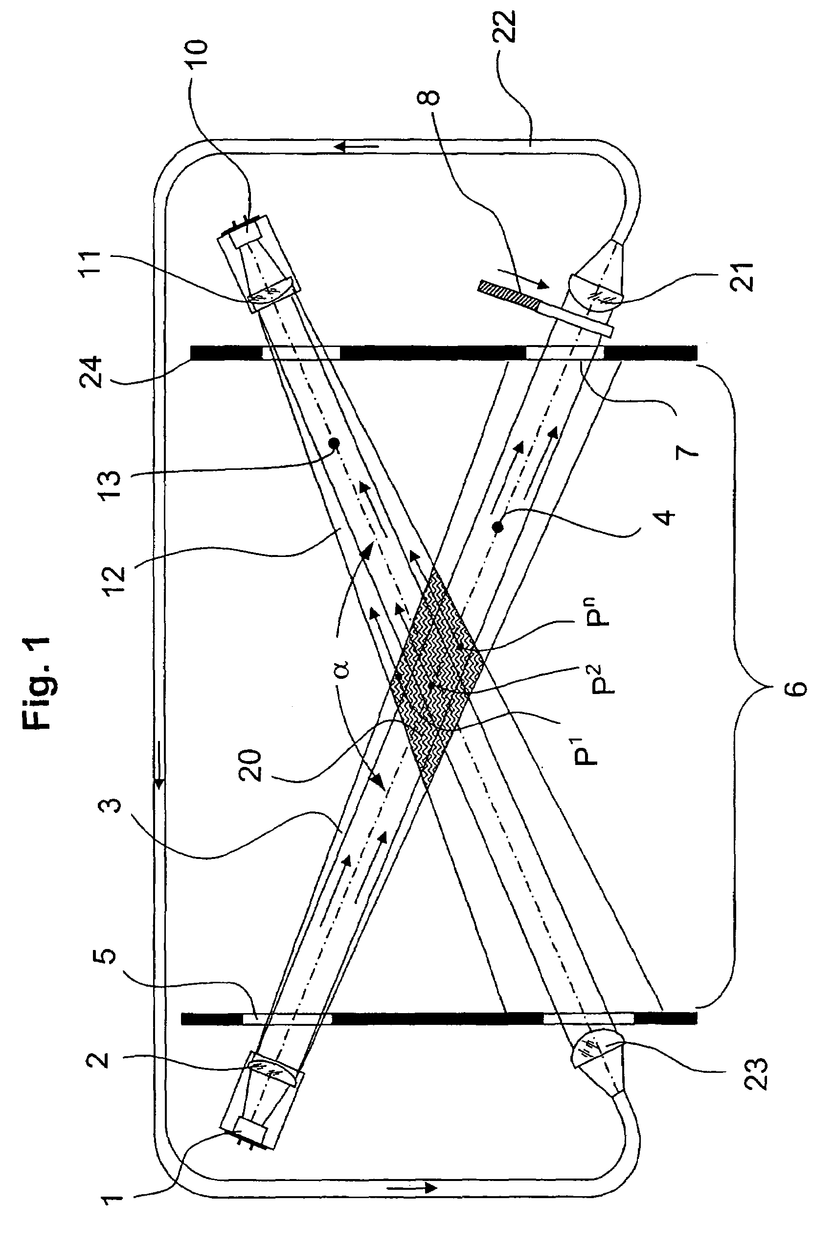
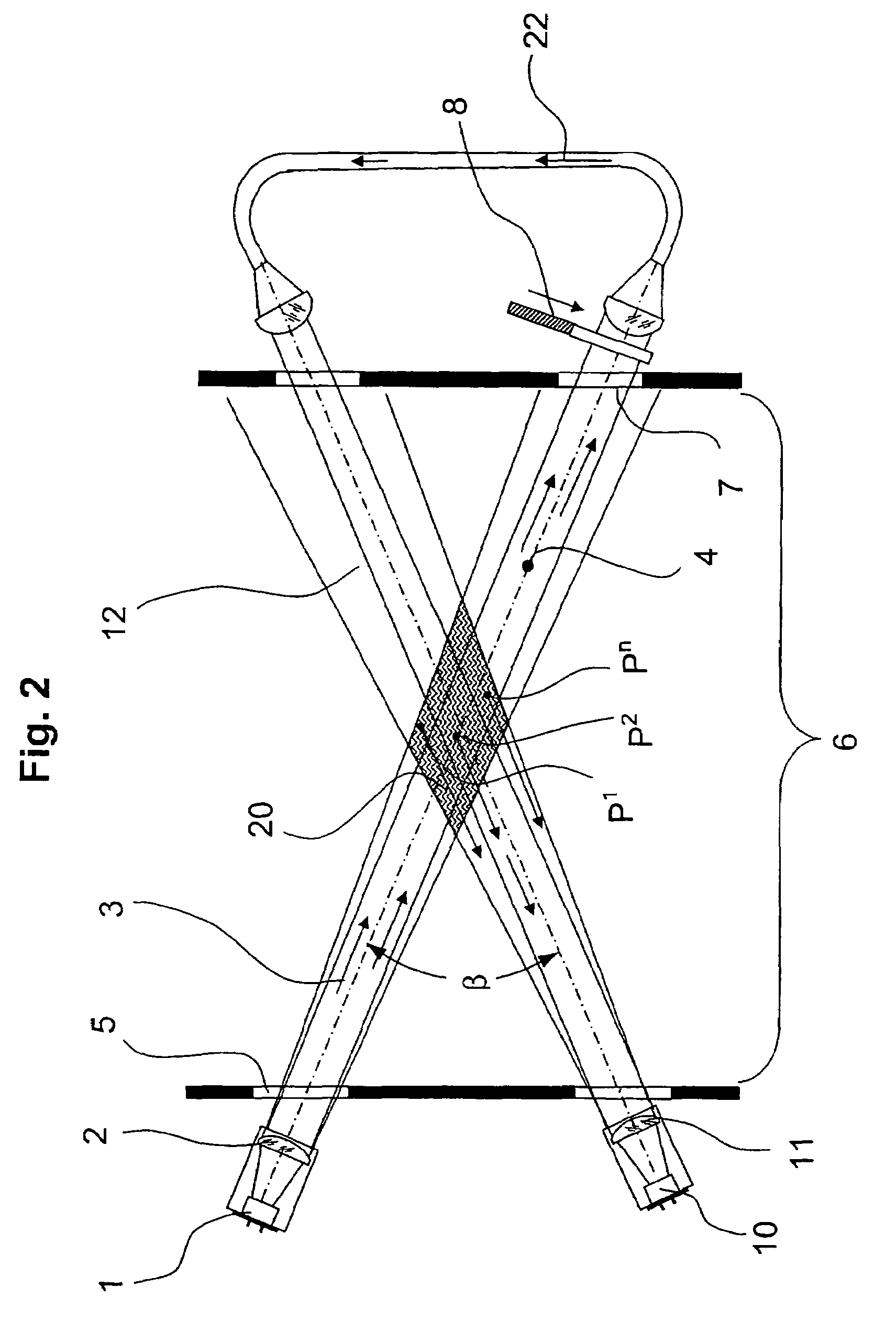
[0024]Referring to FIG. 1, a light emitter 1 that cooperates with an associated emitting optics 2 directs an emitted light beam 3 along an axis 4 of an emitted light beam 3. The light beam 3 traverses an optical end plate 5 from which it enters a testing space 6. The light beam 3 continues and reaches another end plate 7 at the opposite end of testing space 6. After light beam 3 has traversed end plate 7, it reaches an optical shutter 8 which prevents the further expansion of the beam while scattered light is being measured.

[0025]A light receiver 10 which includes a receiving optics 11 is arranged behind a boundary 24 of testing space 6. Light receiver 10 together with receiving optics 11 collect all light that is received from a received light beam 12 and convert the received light quantity into a proportional electrical signal. Received light beam 12 has a received light beam axis 13 which crosses the emitted light beam axis 4 inside testing space 6 at an angle α Since the two lig...


PUM


Abstract

A method and apparatus for determining a range of sight which are capable of monitoring and correcting the operability of the instrument. A light emitter directs an emitted light beam to a measurement zone and a light receiver receives a received light beam from the measurement zone. The emitted light beam and the received light beam cross each other in the measurement zone. A deflector deflects at least a portion of the emitted light beam downstream of the measurement zone along a light transmitting path and directs the portion of the emitted light beam into the received light beam at a side of the measurement zone opposite from the light receiver. An optical shutter intermittently closes the light transmitting path in a temporally controlled manner.

Description

RELATED APPLICATIONS[0001]This application claims the priority of European patent application No. 05 027 138.6 filed Dec. 13, 2005, the disclosure of which is incorporated herein by reference.BACKGROUND OF THE INVENTION[0002]The invention concerns a scattered light range of sight measurement instrument which measures the amount of light scattered by a light beam as it traverses a gas sample from which the density of particulates in the gas sample can be established. With this information, the sight range or viewable distance through the sample can be determined.[0003]Stray or scattered light measuring instruments are used for determining the presence of particles (aerosols, dust, etc.) in venting conduits as well as in the atmosphere as a whole. For example, the carbon particle emissions from a chimney can be determined in this way. Scattered light measuring instruments are further used in street traffic, ocean shipping and air transport, and they are used, when appropriate, to gene...

Claims


Application Information

Patent Timeline
Patent Type & Authority Patents(United States)
IPC IPC(8): G01C3/08
CPCG01N21/538G01N21/532
Inventor KAUFMANN, JUERGENSCHIFFLER, INGOSMETANA, KLAUS
Owner SICK AG
Why Eureka
Try Eureka