
Signal detection contactor and signal calibration system

a contactor and signal technology, applied in the direction of individual semiconductor device testing, semiconductor/solid-state device testing/measurement, instruments, etc., can solve the problems of inability to calibrate differences in timing, difficult to detect signals at the distal end of the probe, and difficult to correctly test the device. , to achieve the effect of reliable detection of signals, excellent rf characteristics and stable contact sta

Inactive Publication Date: 2008-08-19
TOKYO ELECTRON LTD
View PDF14 Cites 2 Cited by
  • Summary
  • Abstract
  • Description
  • Claims
  • Application Information

AI Technical Summary

Benefits of technology

The solution enables reliable detection and calibration of signals, correcting phase differences and ensuring accurate testing of semiconductor devices by maintaining stable contact and impedance matching, even with high-frequency RF signals.

Problems solved by technology

If the test signals have a phase difference or the like, it is difficult to correctly test the device.
Due to the manufacturing process or the like, however, if the physical characteristics of the signal lines or the like differ slightly, and accordingly the timings at which signals of the respective signal lines arrive differ, this difference in timing cannot be calibrated.
It is, however, difficult to detect the signals at the distal ends of the probes, and accordingly it is difficult to detect and calibrate the difference among the plurality of test signals.

Method used


Image

  • Signal detection contactor and signal calibration system
  • Signal detection contactor and signal calibration system
  • Signal detection contactor and signal calibration system

Examples


Embodiment Construction

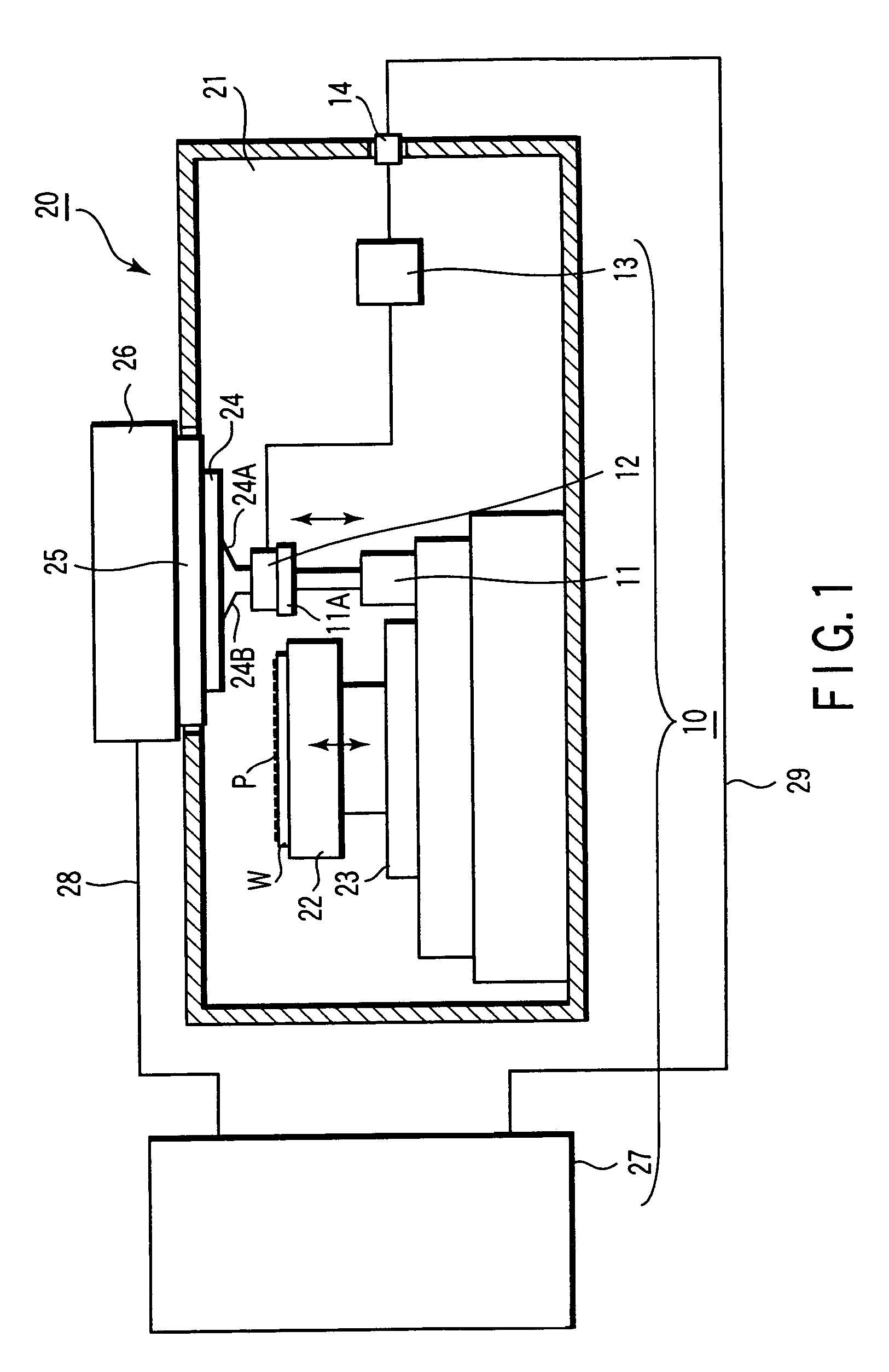
[0038]The invention of the present application provides, in an apparatus which applies a signal from a signal source to a target through at least one terminal, a signal detection contactor to receive and detect the signal to be applied by the terminal to the electrode of the target by coming into contact with the terminal, and a signal calibration system and a method of calibrating a signal to calibrate the signal applied to the target. Various types of apparatuses are used as the apparatus which applies a signal to a target. To describe the invention of the present application more specifically, a prober which tests the electrical characteristics of a device will be described.

[0039]The signal calibration system according to the invention of the present application will be described by way of the embodiment shown in FIGS. 1 to 3. In this embodiment, the signal detection contactor and the method of calibrating a signal according to an embodiment of the invention of the present applic...


PUM


Abstract

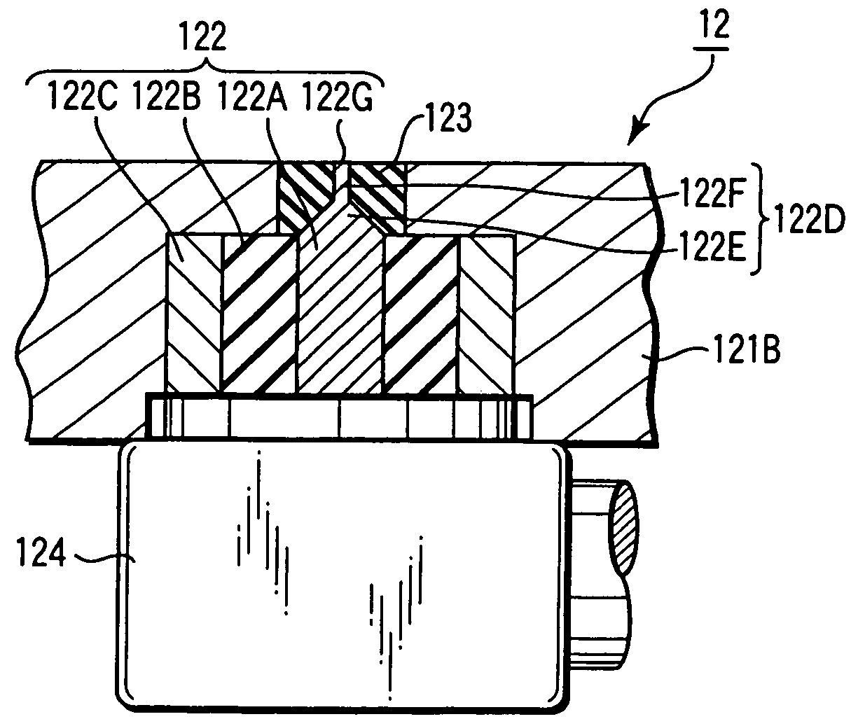
A signal detection contactor has a contactor main body and a plurality of coaxial bodies. Each coaxial body includes a core wire. The core wire is used for coming into contact with a probe of a prober and for receiving a signal transmitted from a tester, in order to calibrate a phase difference among signals transmitted through a plurality of probes.

Description

[0001]This application is based upon and claims the benefit of priority under 35 U.S.C. § 120 from U.S. application Ser. No. 10 / 485,259, filed Feb. 9, 2004, which is a national stage of PCT / JP03 / 02576, filed Mar. 5, 2003, and under 35 U.S.C. § 119 from the prior Japanese Patent Application No. 2002-114950, filed Apr. 17, 2002, the entire contents of which are incorporated herein by reference.TECHNICAL FIELD[0002]The present invention relates to a signal detection contactor and signal calibration system used when calibrating a signal for testing the electrical characteristics of, e.g., a high-speed device.BACKGROUND ART[0003]In the manufacturing process for a semiconductor device or the like, when testing the electrical characteristics of a target test object (to be referred to as “device” hereinafter) formed on a wafer-like substrate (to be merely referred to as “wafer” hereinafter) W, a prober shown in, e.g., FIGS. 4A and 4B, is used. The prober has a loader chamber 1 and prober ch...

Claims


Application Information

Patent Timeline
Patent Type & Authority Patents(United States)
IPC IPC(8): G01R31/28G01R1/04G01R1/06G01R1/067G01R35/00H01L21/66
CPCG01R35/005G01R1/0416G01R31/2889G01R31/26H01L22/00
Inventor WATANABE, CHIHIRO
Owner TOKYO ELECTRON LTD
Learn More