
Energy active composite yarn, methods for making the same, and articles incorporating the same

a composite yarn and energy-active technology, applied in the field of energy-active textile yarns, can solve the problems of difficult handling, short planar fibers that are limited, and the current process for integrating electronic functionality on such a curved surface is complex

Active Publication Date: 2008-08-19
ADIDAS
View PDF39 Cites 47 Cited by
  • Summary
  • Abstract
  • Description
  • Claims
  • Application Information

AI Technical Summary

Benefits of technology

The composite yarns achieve mechanical integrity, stretch, and recovery properties, enabling them to perform high-level electronic functions while maintaining textile characteristics, suitable for knitted, woven, or nonwoven fabrics and wearable garments.

Problems solved by technology

This technique provides short planar fibers that are limited by the wafer surface (of length of about 42 mm and cross section of 35×1 μm) and can be difficult to handle.
Although continuous filaments can be produced by this process based on inherently semiconductive materials, integrating electronic functionality on such a curved surface currently requires a complex process that has yet to be demonstrated along the length of the fiber.
Further, the Clemens and Mathewson approaches are based on traditional silicon semiconductor manufacturing processes, which may present further limitations with regard to cost, process scalability, and complexity of the electronic functionalities that can be achieved.
In addition, the mechanical characteristics of the resulting fibers may fail to possess desired textile characteristics.
Although adequate electrical characteristics of the resulting fiber transistors have been reported for this fabrication method, such method is impractical for producing fibers on a large scale basis.
Although this patent discloses an apparatus based on fiber and fabric predetermined forms and patterns, it does not disclose a way to fabricate the fibers so as to create the desired electronic and opto-electronic functionalities.
Although this process may lead to functional fibers, the process conditions and material deposition may severely affect the original fiber properties, with subsequent loss of characteristics required for textile processing.
Although this process may lead to functional fibers and may be suitable from a manufacturing point of view, material deposition over the fiber surface may severely affect the original fiber properties with subsequent loss of characteristics required for textile processing.
Also, with the layer-by-layer approach it can be difficult to achieve the desired durability and electrical performance in the final system.
Such methods may fail to produce embedded electronic functionalities that are highly resistant to fracture during mechanical deformation, for example during bending or flexing as occurs in textile processing.
In addition, none of the above disclosures appears to provide a fiber that can keep its original textile characteristics.
Moreover, no disclosure appears to provide a fiber with elastic stretch and recovery properties.
In this regard, the inability of a fiber to stretch and recover from stretch is a notable limitation in applications in which stretch and recovery properties are important (such as in many types of wearable articles and apparel).
Furthermore, if integration of such functional fibers into the textile structure requires that the textile electronic functionality be rendered through the contacts provided by the functional fibers, the curved non-planar geometry of the fiber may not be the optimum for an acceptable electrical performance.

Method used


Image

  • Energy active composite yarn, methods for making the same, and articles incorporating the same
  • Energy active composite yarn, methods for making the same, and articles incorporating the same
  • Energy active composite yarn, methods for making the same, and articles incorporating the same

Examples


example

[0089]A specific embodiment of the present invention will now be described by way of the following Example, which is for the purpose of illustration only.

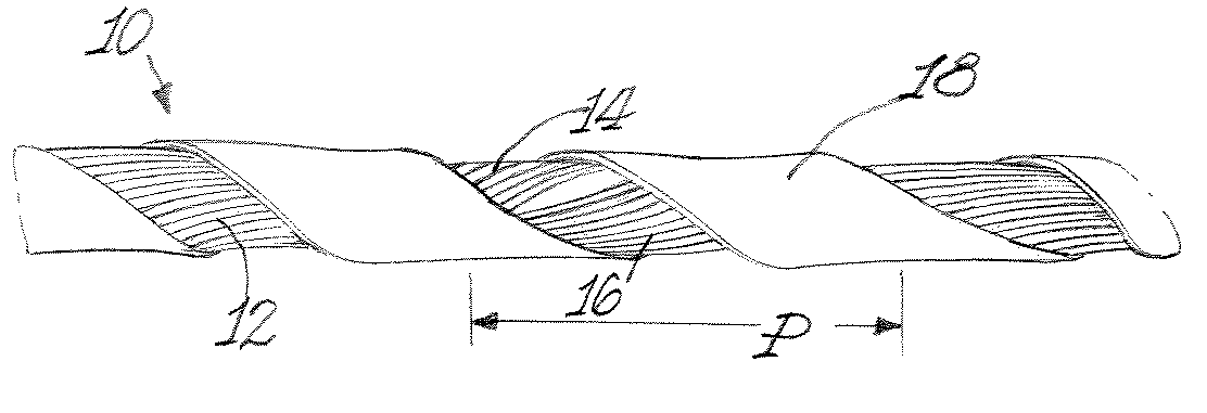
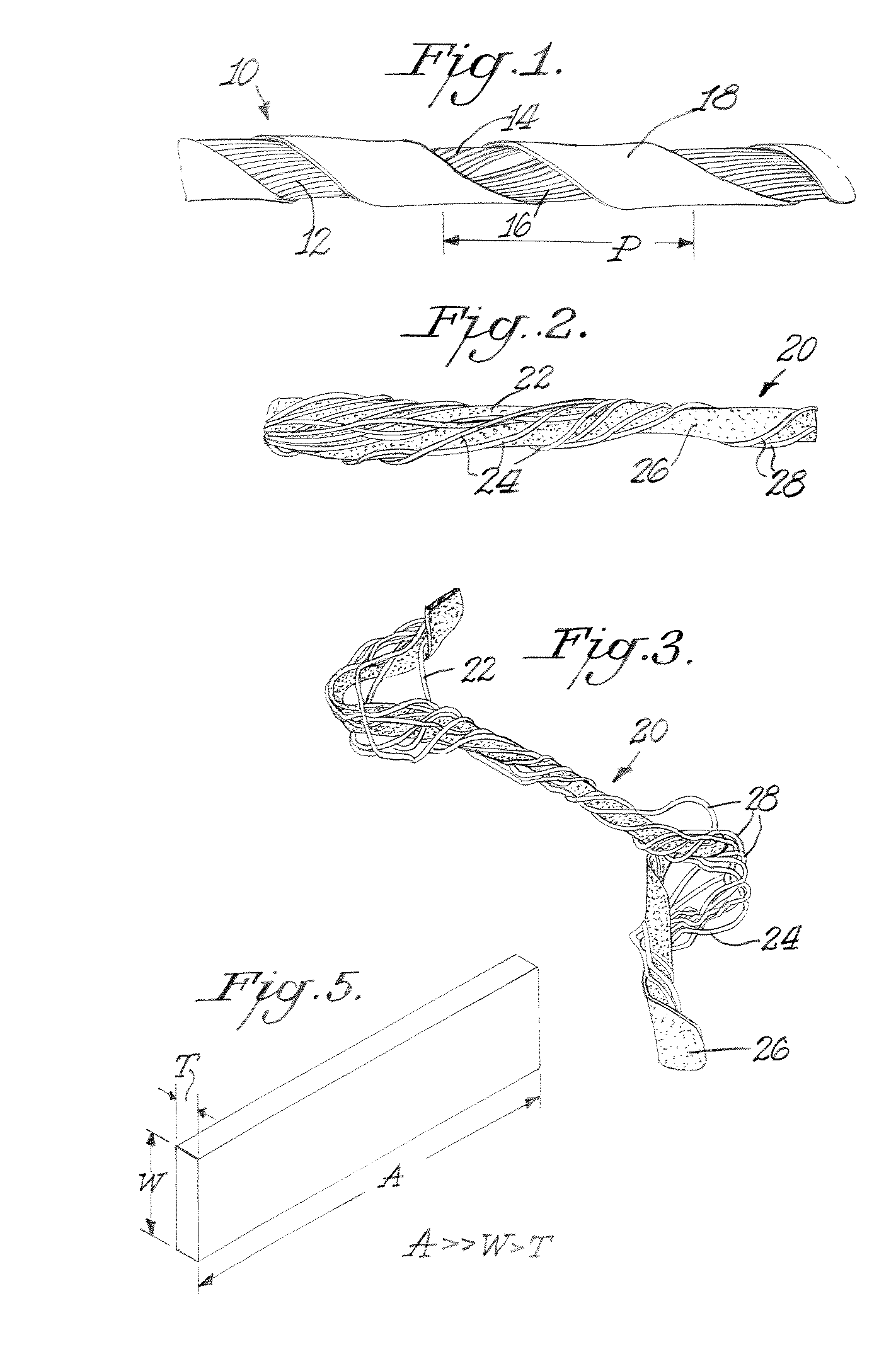
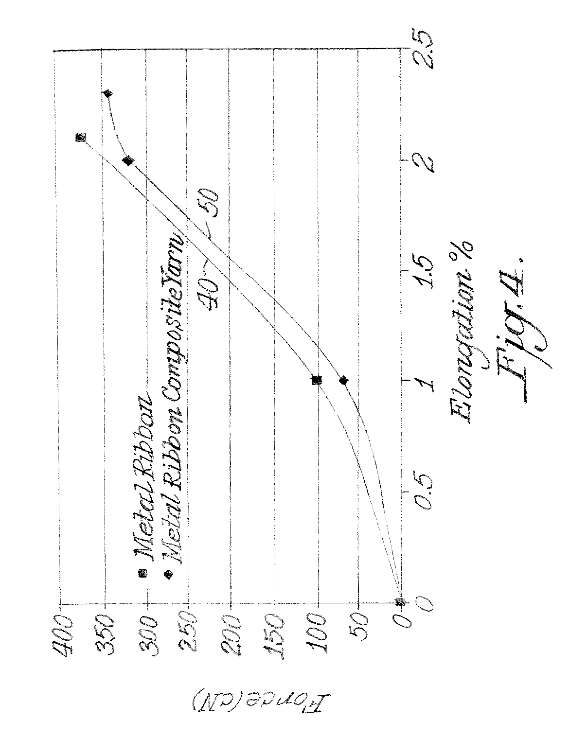
[0090]A composite yarn was made by wrapping a 78 decitex (dtex) elastic core made of Lycra® spandex yarn with a flat metal ribbon having a thickness (T) of 40 μm and a width (W) of 210 μm obtained from Rea Magnet Wire Company, Inc., USA. The Lycra® spandex elastic core yarn was first drafted to a value of 3.6 times (i.e., N=3.6) and then wrapped at 250 turns / meter (turns of flat ribbon per meter of drafted Lycra® spandex yarn) with a single length of the flat metal ribbon twisted in the “S” direction. An electrically conductive composite yarn having a planar element was produced. The flat metal ribbon covering was done using a standard process on an I.C.B.T. machine, model G307.

[0091]The stress-strain properties of the metal ribbon (40) alone and of the composite yarn (50) of this Example are shown in FIG. 4. The composite yarn (50...


PUM

PropertyMeasurementUnit
lengthaaaaaaaaaa
lengthaaaaaaaaaa
diameteraaaaaaaaaa

Abstract

Energy active composite yarns include at least one textile fiber member of either an elastic or inelastic material, and at least one functional substantially planar filament, which surrounds or covers the textile fiber member. The composite yarns can include an optional stress-bearing member, which also surrounds or covers the textile fiber member. The composite yarns may be multifunctional, meaning the functional substantially planar filament can exhibit combinations of electrical, optical, magnetic, mechanical, chemical, semiconductive, and / or thermal energy properties.

Description

FIELD OF THE INVENTION[0001]The present invention relates to energy active textile yarns. In particular, this invention relates to textile yarns containing electrically or opto-electrically active planar elements distributed along at least a portion of the length of the textile yarn, a process for producing the same, and to fabrics, garments, and other articles incorporating such yarns. Such yarns can be constructed to be multifunctional yarns, meaning that the planar elements can exhibit combinations of electrical, optical, magnetic, mechanical, chemical, semiconductive, and / or thermal energy properties.BACKGROUND OF THE INVENTION[0002]Fibers and filaments that have an active functionality when connected to an energy source have been included in textile yarns. Such functional fibers and filaments can include electrically conductive metallic wires or stainless steel fibers for the purpose of conducting electrical current, transmitting signals or data, shielding from electromagnetic ...

Claims


Application Information

Patent Timeline
Patent Type & Authority Patents(United States)
IPC IPC(8): D02G3/00D03D15/56H10N10/00H10N15/00
CPCD02G3/328D02G3/441Y10T428/2936Y10T428/2924Y10T428/2933
Inventor KARAYIANNI, ELENICOULSTON, GEORGE W.MICKA, THOMAS A.
Owner ADIDAS
Learn More