
Optical detection and location of gunfire

a technology of optical detection and location, applied in the direction of direction/deviation determining electromagnetic system, instruments, etc., can solve the problems of repetitive and dangerous hazards, insufficient location of sniper shooters to accurately return defensive fire, and significant hazard to deployed soldiers and the public at large, so as to increase the resolution of images, and increase the magnification and resolution of images

Inactive Publication Date: 2008-08-12
UNITED STATES OF AMERICA THE AS REPRESENTED BY THE SEC OF THE ARMY
View PDF8 Cites 35 Cited by
  • Summary
  • Abstract
  • Description
  • Claims
  • Application Information

AI Technical Summary

Benefits of technology

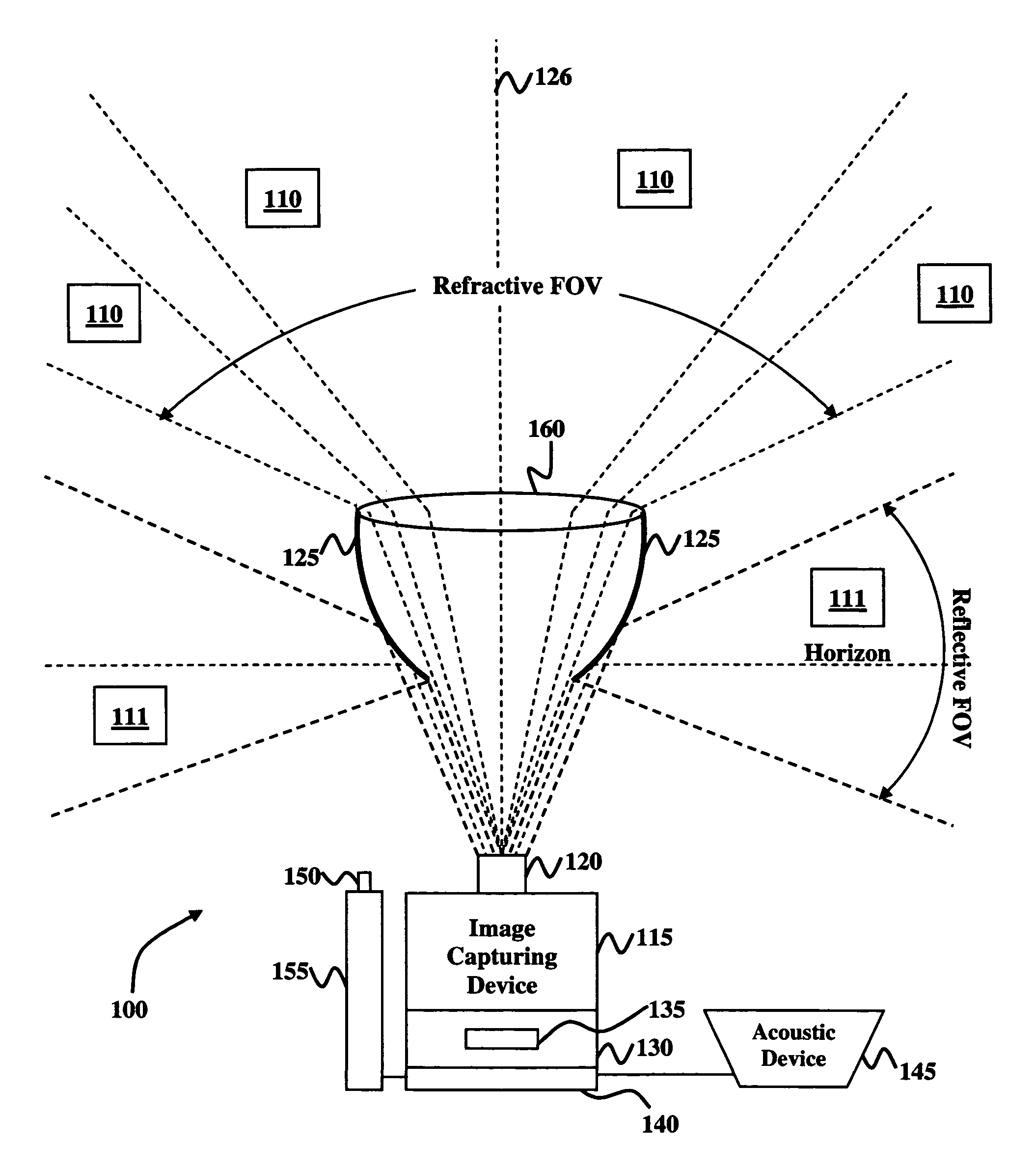
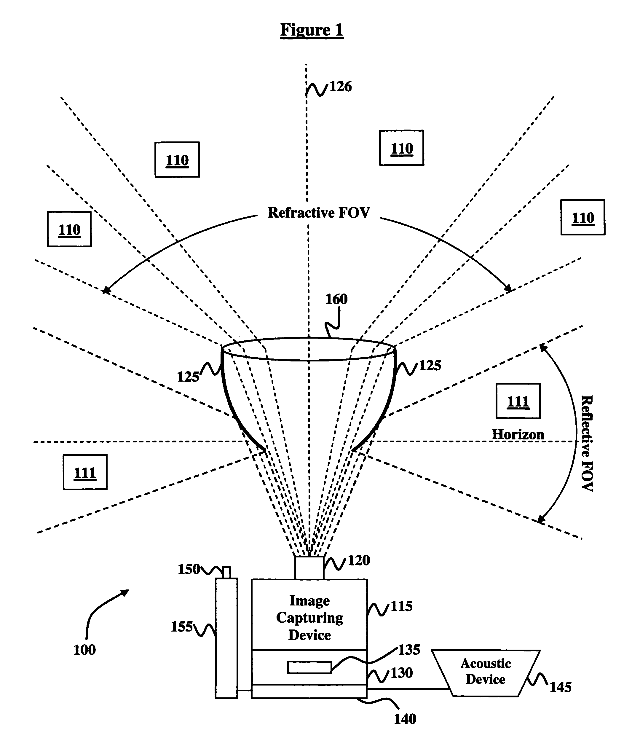
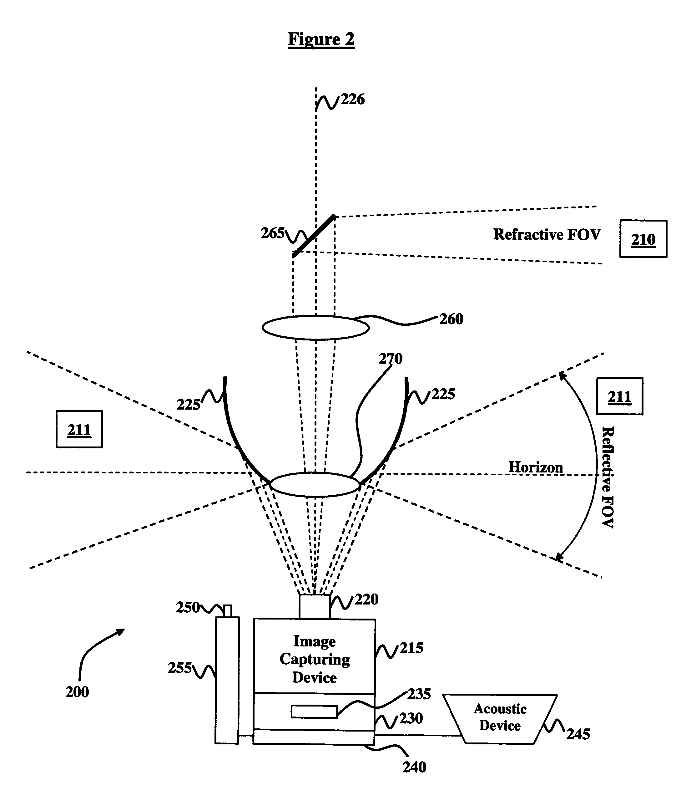
[0011]The optical gunfire detection system may further comprise a mirror, wherein the mirror is positioned along an axis of the parabolic reflector, and wherein the mirror provides an increased resolution of the images; and a zoom lens positioned between the mirror and the image-capturing device, wherein the zoom lens provides an increased magnification and resolution of the images.
[0012]The invention also comprises a method of detecting sniper gunfire comprising observing images in a field-of-view using a convex parabolic reflector; transmitting the images to an image-capturing device, wherein the image-capturing device detects light, wherein the light comprises any of ultraviolet, visible, or infrared light; storing the images in an image storage device, wherein the image storage device comprises a solid-state digital memory unit operable to store multiple seconds of video imagery; using a real-time computer-implemented mechanism connected to the image storage device to detect locations and classifications of gunfire associated with the images; verifying the classifications of the gunfire using an acoustic device in communication with the computer-implemented mechanism; and identifying the locations of the gunfire using a position or designator laser. The method further comprises partially restricting transmission of the light using a narrowband Fraunhofer line filter; providing an azimuthal field-of-view of 360-degrees using the convex parabolic reflector; defending against a source of the gunfire using a defense mechanism; providing an axial field-of-view using a lens system, wherein the lens system is positioned along an axis of the parabolic reflector; and increasing the resolution of the images using a mirror, wherein the mirror is positioned along the symmetry axis of the parabolic reflector. Also, the method comprises increasing the magnification and resolution of the images using a zoom lens positioned in between the mirror and the image-capturing device.
[0013]The invention provides a relatively simple optical system with a very large view of the surrounding environment and with digital video storage capabilities for detecting sniper gunfire. Also, the invention provides optical confirmation of a gunfire event by using an acoustic device in communication with a computer-implemented mechanism, thereby reducing false alarms. Moreover, the invention provides verification of the direction from which the shot was fired with improved accuracy and precision. Additionally, the invention provides the approximate range to the shooter based on the time from the optically detected muzzle flash to the acoustic detection of the associated sound. Furthermore, the invention provides a digital video image of the gunfire location, providing a means for locating and pursuing the shooter, and for retaliation. In addition to the above, the invention also provides for the classification and identification of the weapon used based on the combination of optical and acoustic, spectral, spatial, and temporal signatures.

Problems solved by technology

Snipers present a significant hazard to deployed soldiers and to the public at large.
Single-shot gunfire events are difficult to locate, thus snipers tend to escape detection and, in the absence of credible detection and retaliation capability, constitute a repetitive and dangerous hazard.
Therefore, the location of the sniper shooter may not be sufficiently precise to accurately return defensive fire.
Further, optical systems may not provide a very wide field-of-view, thereby limiting the probability of detecting gunfire at any given moment.
The lack of an efficient wide field-of-view optical weapon fire detection system may be a significant handicap in current military operations as well as in pseudo-military and non-military settings.

Method used


Image

  • Optical detection and location of gunfire
  • Optical detection and location of gunfire
  • Optical detection and location of gunfire

Examples


Embodiment Construction

[0022]The invention and the various features and advantageous details thereof are explained more fully with reference to the non-limiting embodiments that are illustrated in the accompanying drawings and detailed in the following description. It should be noted that the features illustrated in the drawings are not necessarily drawn to scale. Descriptions of well-known components and processing techniques are omitted so as to not unnecessarily obscure the invention. The examples used herein are intended merely to facilitate an understanding of ways in which the invention may be practiced and to further enable those of skill in the art to practice the invention. Accordingly, the examples should not be construed as limiting the scope of the invention.

[0023]As previously mentioned, there is a need for a very large field-of-view optical system and video capturing mechanism for image storage to detect and document gunfire events, and to provide means for identification of and retaliation ...


PUM


Abstract

Disclosed is an optical gunfire detection system comprising an image-capturing device operable for detecting light; a narrowband Fraunhofer line filter connected to the image-capturing device, and operable for partially restricting transmission of the light; a convex parabolic reflector operable for transmitting images to the image-capturing device; a lens system; an image storage device connected to the image-capturing device, wherein the image storage device comprises a solid-state digital memory unit operable to store multiple seconds of video imagery; a real-time computer-implemented mechanism connected to the image storage device, the computer-implemented mechanism operable for detecting locations and classifications of gunfire associated with the images; an acoustic device in communication with the computer-implemented mechanism, and operable for verifying the classifications of the gunfire; a position laser operable for identifying the locations of the gunfire; and a defense mechanism comprising the laser pointer and operable to defend against a source of the gunfire.

Description

GOVERNMENT INTEREST[0001]The invention described herein maybe manufactured, used, and / or licensed by or for the United States Government.BACKGROUND OF THE INVENTION[0002]1. Field of the Invention[0003]The invention generally relates to weapon fire detection, and more particularly to a hemispherical field-of-view optical system and method for the detection and location of sniper gunfire.[0004]2. Description of the Related Art[0005]Snipers present a significant hazard to deployed soldiers and to the public at large. Single-shot gunfire events are difficult to locate, thus snipers tend to escape detection and, in the absence of credible detection and retaliation capability, constitute a repetitive and dangerous hazard. A sniper shot can be detected both by the muzzle blast and by the bullet shock wave. A conventional acoustic array can determine the direction and range from which the shot is fired with reasonable accuracy, and may provide classification and possible identification of t...

Claims


Application Information

Patent Timeline
IPC IPC(8): F41G3/04
CPCF41G3/147G01S11/16G01S5/16G01S5/28G01S3/784G01S3/8083
Inventor BEEKMAN, DANIEL W.
Owner UNITED STATES OF AMERICA THE AS REPRESENTED BY THE SEC OF THE ARMY
Learn More