Die cushion controlling apparatus and die cushion controlling method
a technology of die cushion and controlling apparatus, which is applied in the direction of forging/pressing/hammering apparatus, forging press, shape safety device, etc., can solve the problems of throttling workability, severe maintenance and management, complicated structure of hydraulic apparatus, etc., and achieve high accuracy, control of the pressure of the cushion pad, and improvement of the workability of the press
- Summary
- Abstract
- Description
- Claims
- Application Information
AI Technical Summary
Benefits of technology
Problems solved by technology
Method used
Image
Examples
first embodiment
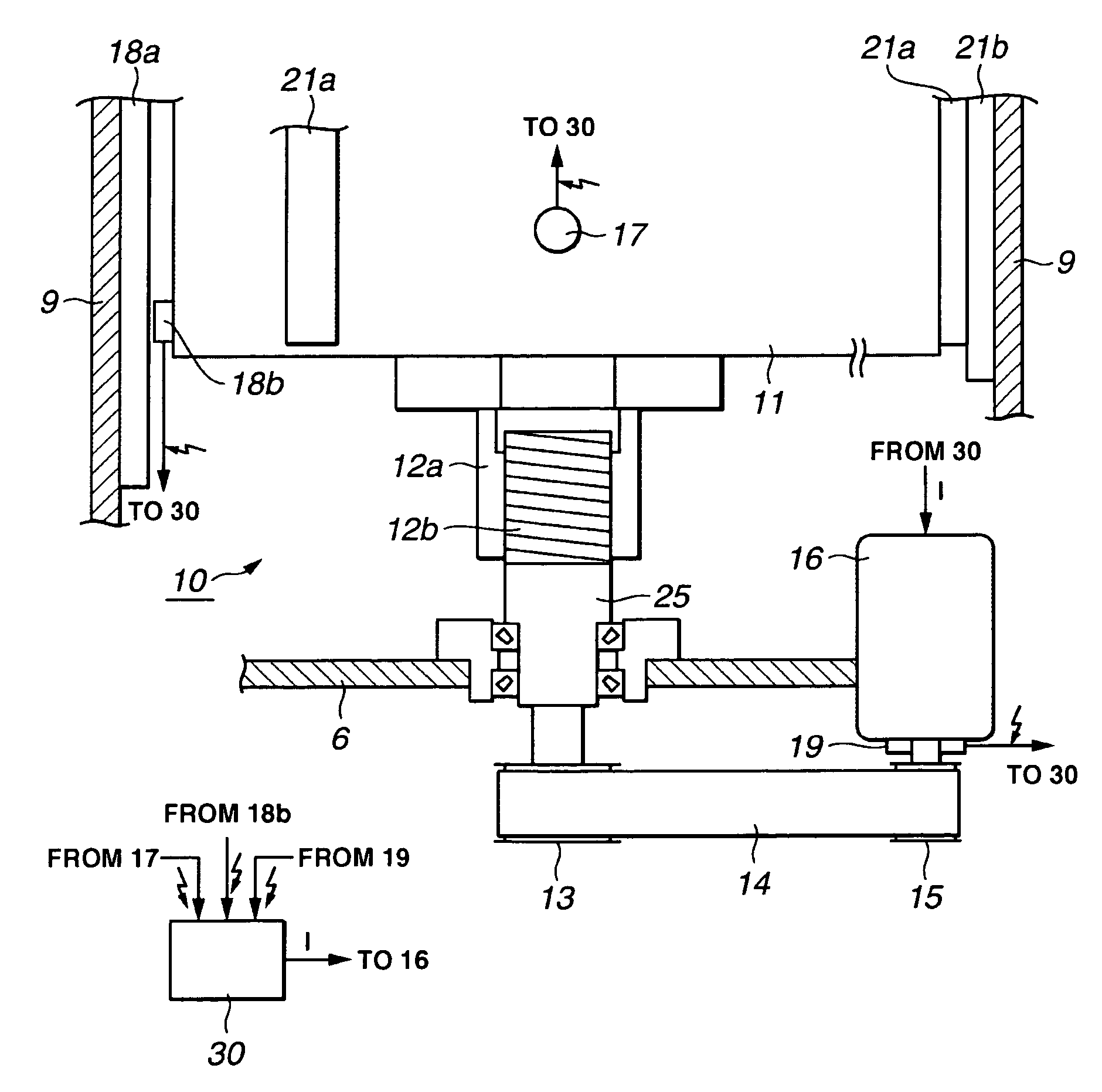
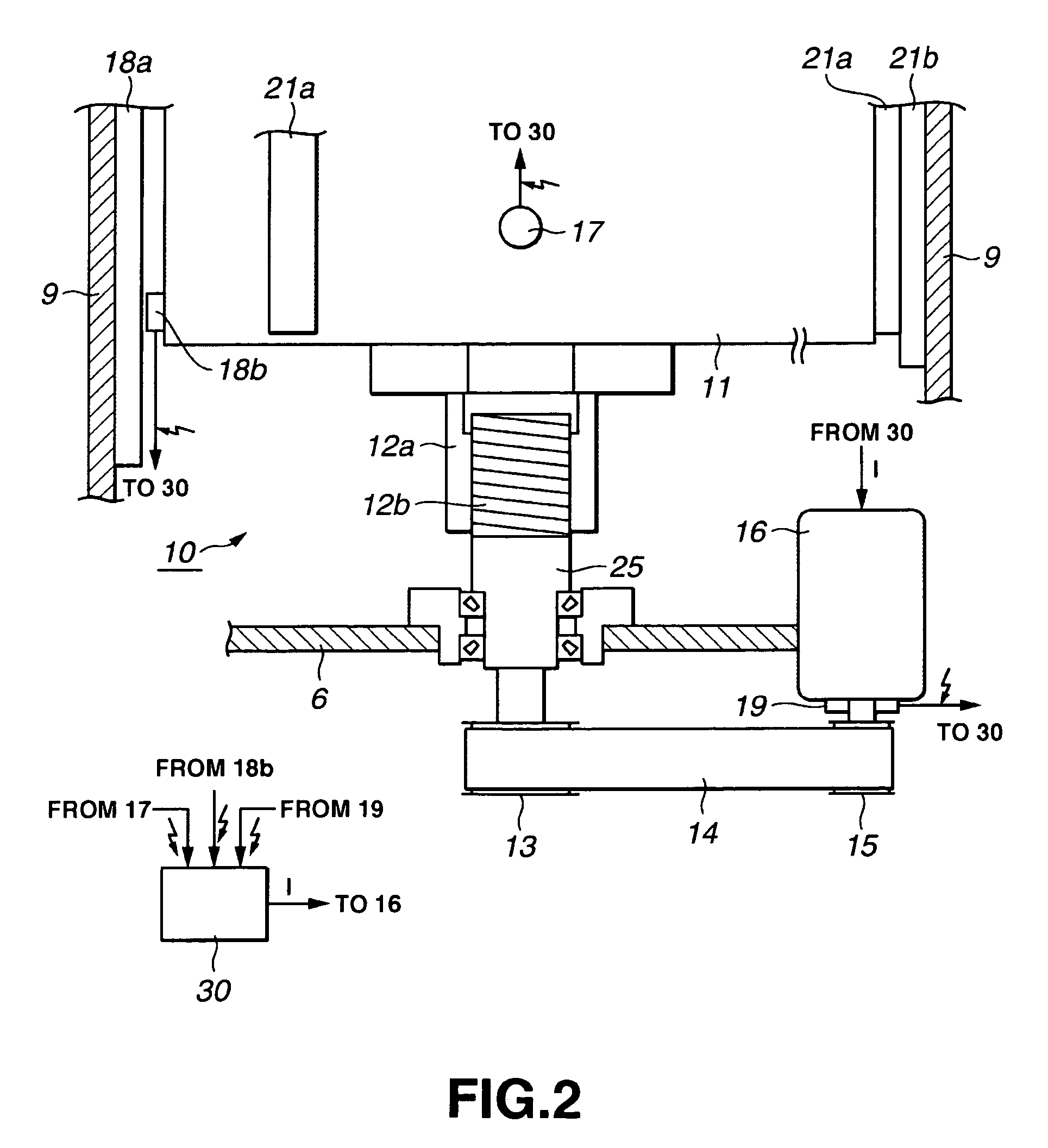
[0064]FIG. 2 is a schematic view of the die cushion according to the first embodiment. FIG. 3 is a top view of the die cushion according to the first embodiment.
[0065]In the die cushion 10, the cushion pad 11 is coupled to the rotary shaft of a servomotor 16 via a ball screw 12, a coupling member 25, a large pulley 13, a belt 14 and a small pulley 15. Powers of the cushion pad 11 and the servomotor 16 are transmissible to each other. A nut portion 12a of the ball screw 12 is coupled to a lower portion of the cushion pad 11. A threaded portion 12b of the ball screw 12 is engaged with the nut portion 12a. A lower part of the threaded portion 12b is connected to the coupling member 25. The coupling member 25 is supported to the beam 6 by a bearing, etc. and its lower part is coupled to the large pulley 13. The small pulley 15 is connected to the rotary shaft of the servomotor 16. The belt 14 is wound on the large pulley 13 and the small pulley 15, and the powers of the large pulley 13 ...
second embodiment
[0089]FIG. 6 is a schematic view of a die cushion according to the second embodiment. Concerning the die cushion 50 shown in FIG. 6, only different portion from the die cushion 10 shown in FIG. 2 will be described.
[0090]In the die cushion 50, the cushion pad 11 is coupled to a rotary shaft of the servomotor 16 via a ball screw 52, a coupling member 55, a large pulley 13, a belt 14 and a small pulley 15. Between the cushion pad 11 and the servomotor 16, powers are transmissible to each other. The threaded portion 52b of the ball screw 52 is coupled to the lower portion of the cushion pad 11. The threaded portion 52b of the ball screw 52 is engaged with a nut portion 52a. A lower part of the nut portion 52a is connected to the coupling member 55. The coupling member 55 is supported by a bearing, etc. to the beam 6, and its lower portion is coupled to the large pulley 13. The small pulley 15 is connected to the rotary shaft of the servomotor 16. A belt 14 is wound around the large pull...
third embodiment
[0094]FIG. 7 is a schematic view of a die cushion according to a third embodiment. FIG. 8 is a top view of the die cushion according to the third embodiment. Concerning the die cushion 60 shown in FIG. 7 and FIG. 8, only a portion different from the die cushion 10 shown in FIG. 2 will be described.
[0095]A linear servomotor 61 is provided between each side face of the cushion pad 11 and each inner wall surface of the bed 9 opposed to the side face of the cushion pad 11. The linear servomotor 61 includes a pair of a coil portion 61a and a magnet portion 61b. The coil portion 61a is provided on each side face of the cushion pad 11, and the magnet portion 61b is provided on the inner wall surface of the bed 9. Contrarily, the magnet portion 61b may be provided on each side face of the cushion pad 11, and the coil portion 61a may be provided on the inner wall surface of the bed 9. Incidentally, in FIG. 7, the linear servomotor 61 is shown only on the right side face of the cushion pad 11...
PUM
| Property | Measurement | Unit |
|---|---|---|
| energizing force | aaaaa | aaaaa |
| generating time | aaaaa | aaaaa |
| time | aaaaa | aaaaa |
Abstract
Description
Claims
Application Information
 - R&D
- Intellectual Property
- Life Sciences
- Materials
- Tech Scout
- Unparalleled Data Quality
- Higher Quality Content
- 60% Fewer Hallucinations
Browse by: Latest US Patents, China's latest patents, Technical Efficacy Thesaurus, Application Domain, Technology Topic, Popular Technical Reports.
© 2025 PatSnap. All rights reserved.Legal|Privacy policy|Modern Slavery Act Transparency Statement|Sitemap|About US| Contact US: help@patsnap.com


