
Image forming apparatus

a technology of forming apparatus and forming plate, which is applied in the direction of digitally marking record carriers, instruments, printing, etc., can solve the problems of limiting the performance of cpu, low performance of pci that passes through the chip-set, and not being made open by cpus

Active Publication Date: 2008-07-29
RICOH KK
View PDF0 Cites 2 Cited by
  • Summary
  • Abstract
  • Description
  • Claims
  • Application Information

AI Technical Summary

Benefits of technology

The invention is an image forming apparatus that solves problems in conventional technology. It includes a controller with an integrated circuit for image processing and an engine unit with a scanner and a plotter. The controller has a switching controller that controls whether to output the scanner image data to the engine interface or to the chip-set interface, and a combining controller that combines multiple scanner image data to generate one scanner image data. The technical effects of this invention include improved image quality, faster processing, and better data management.

Problems solved by technology

However, interfaces of conventional CPUs are made open, but interfaces of recently available reduced instructions set computer (RISC)-type general-purpose CPUs are not made open.
Therefore, it is necessary to connect the ASIC with the CPU via a chip-set, which restricts the performance of the CPU.
However, the PCI that passes through the chip-set has low performance.
Therefore, the PCI is not suitable for structuring an image forming apparatus such as a printer and a copying machine.
Consequently, when the CPU whose interface is not made open is utilized for the controller of the image forming apparatus, how properly data is to be transferred between the chip-set of the CPU and the engine and how best to execute a high-speed image formation processing are extremely important issues.
Therefore, how to solve the reduction in performance is an extremely important issue.
When the image data combining function is executed, how to achieve a high-speed image formation processing is an extremely important issue as well.

Method used


Image

  • Image forming apparatus
  • Image forming apparatus
  • Image forming apparatus

Examples


first embodiment

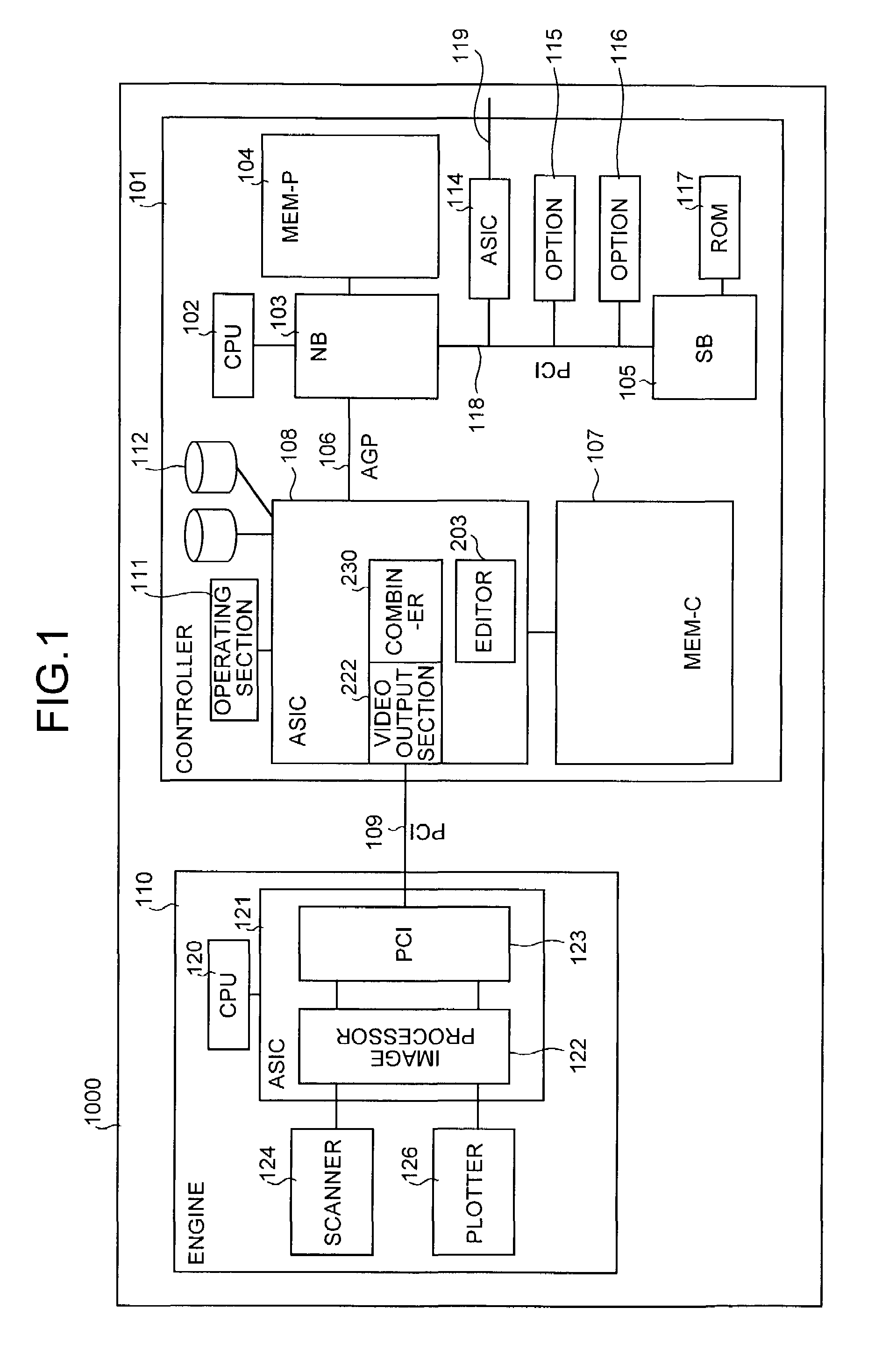
[0039]FIG. 1 shows a total configuration of an image forming apparatus (hereinafter, “multi-function machine”) according to a As shown in FIG. 1, this multi-function machine 1000 has a controller 101 and an engine section 110 connected to each other via a PCI 109. The controller 101 controls the whole of the multi-function machine, and controls drawing, communications, and an input through an operating section 111. The engine section 110 has a scanner 124 and a plotter 126. The plotter 126 is a black and white plotter, or a one-drum color plotter. The scanner 124 is a scanner or a facsimile unit. The engine section 110 has an ASIC 121 including an image processor 122 that carries out image processing such as error diffusion or gamma conversion and a PCI 123, and a CPU 120, in addition to the plotter 126 and the scanner 124 that are so-called an engine part.

[0040]The controller 101 has a CPU 102, a north bridge (NB) 103, a system memory (MEM-P) 104, a south bridge (SB) 105, a local ...

second embodiment

[0169]As explained above, the multi-function machine has the combiners 2030a to 2030d and the editor 2003 provided not within the engine section 110, but within the ASIC 108 connected to the NB 103 via the AGP bus 106. Therefore, it is possible to combine a plurality of image data at a high speed. As a result, it is possible to improve the performance of the image formation processing that includes the combining of a plurality of image data by the multi-function machine 1000 with the four-drum color plotter.

[0170]In the first and second embodiments, the controller according to the present invention is mounted on the multi-function machine but the application is not limited to this. It is also possible to apply the invention to other image forming apparatuses that carry out an image formation processing, such as a printer and a copying machine.

[0171]As explained above, according to one aspect of the present invention, when a CPU whose interface is not made open is utilized for the c...


PUM


Abstract

An image forming apparatus includes a controller having an integrated circuit for image processing. The controller is connected to an engine via a peripheral component interconnect (PCI). The engine includes a plotter and a scanner. The controller includes a central processing unit (CPU) to which a chip-set is connected via an accelerated graphics port (AGP). The controller also includes an application specific integrated circuit (ASIC) that controls whether to output scanner image data, which is data acquired by the scanner, to the PCI as plotter data for the plotter, or to output the scanner image data to the AGP, or to output image data input through the AGP to the PCI as plotter data for the plotter. The ASIC includes a combiner that combines a plurality of image data.

Description

BACKGROUND OF THE INVENTION[0001]1) Field of the Invention[0002]The present invention relates to an image forming apparatus that has an engine section having a scanner, a plotter, and a CPU, connected to a controller having an integrated circuit for image processing, thereby to carry out image formation processing under the control of the CPU.[0003]2) Description of the Related Art[0004]Conventionally, in many cases, an image forming apparatus such as a printer or a copying machine has an engine section connected with a controller that includes an application specific IC (ASIC) for image processing and a central processing unit (CPU), and carries out an image formation processing by using this controller.[0005]For example, in the copying machine, the ASIC that has a plurality of hardware elements for image processing is mounted on the controller, and this ASIC and the engine are connected to each other via a peripheral component interconnect (PCI) interface. A CPU and the ASIC are c...

Claims


Application Information

Patent Timeline
Patent Type & Authority Patents(United States)
IPC IPC(8): B41B15/00G06F13/00B41J5/30H04N1/00H04N1/32
CPCH04N1/32502H04N1/32512H04N1/32587H04N1/32529H04N1/00204H04N2201/0082H04N2201/0081
Inventor TANAKA, SATORU
Owner RICOH KK
Learn More