
Steam generator mapping with reflections of eddy current signal

a technology of eddy current signal and steam generator, which is applied in the field of steam generators, can solve the problems of degrading affecting the affecting the thermal hydraulic performance of the component,

Active Publication Date: 2008-07-29
AREVA NP INC
View PDF2 Cites 16 Cited by
  • Summary
  • Abstract
  • Description
  • Claims
  • Application Information

AI Technical Summary

Benefits of technology

"The present invention provides a system and methodology for determining the thicknesses and locations of deposits on the heating surfaces of a steam generator. This is achieved by creating a calibration standard with at least two rings of deposit material, subjecting them to an eddy current signal, and using the reflected signals to obtain a polynomial equation fit of the actual thickness of the rings. The methodology then detects and records reflections of the eddy current signal in the steam generator tubes, and calculates the thickness of the deposits from the recorded reflections and the polynomial equation. This system and methodology minimize the need for workers to enter potentially radioactive environments."

Problems solved by technology

Nuclear steam generators used in pressurized water reactors, for example, are subject to the accumulation of feedwater impurities.
Although the feedwater is maintained at a high level of purity, minute concentrations of corrosion products and / or feedwater impurities may be concentrated in the flow stream, consequently leading to buildup of these materials within the steam generator as the water is converted into steam.
These deposits will eventually degrade the thermal hydraulic performance of the component.
These techniques, however, are prone to error.
Moreover, visual inspections introduce a significant radiological risk to workers if the steam generator is connected to a nuclear power generation system.

Method used


Image

  • Steam generator mapping with reflections of eddy current signal
  • Steam generator mapping with reflections of eddy current signal
  • Steam generator mapping with reflections of eddy current signal

Examples


Embodiment Construction

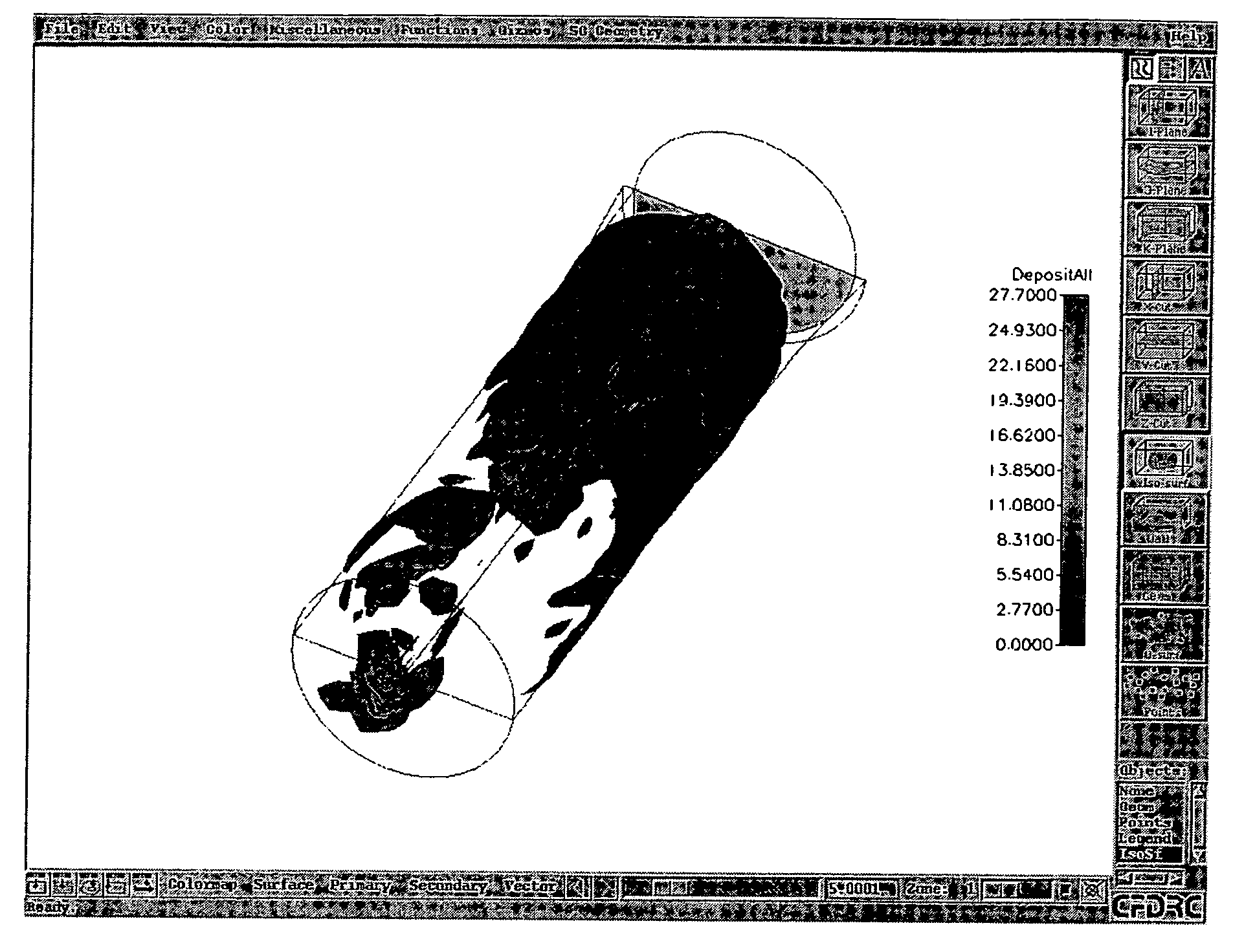
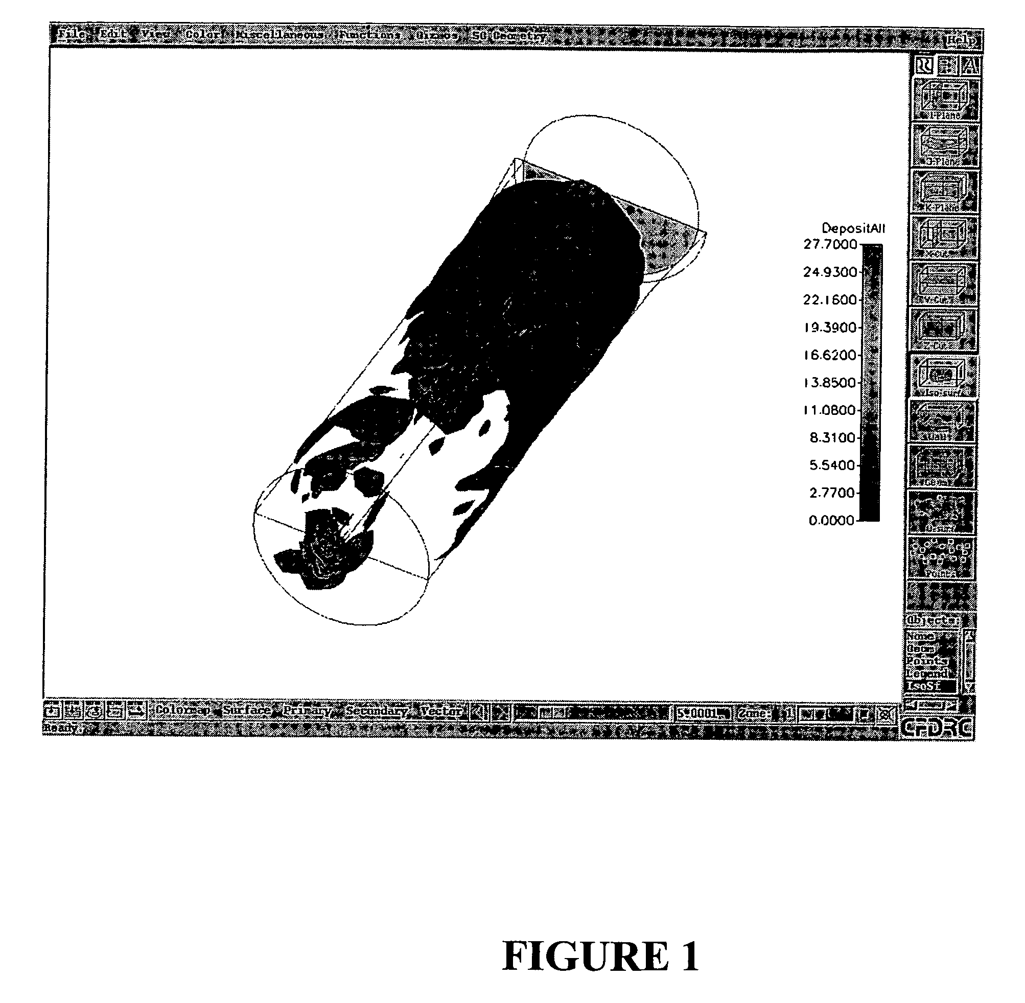
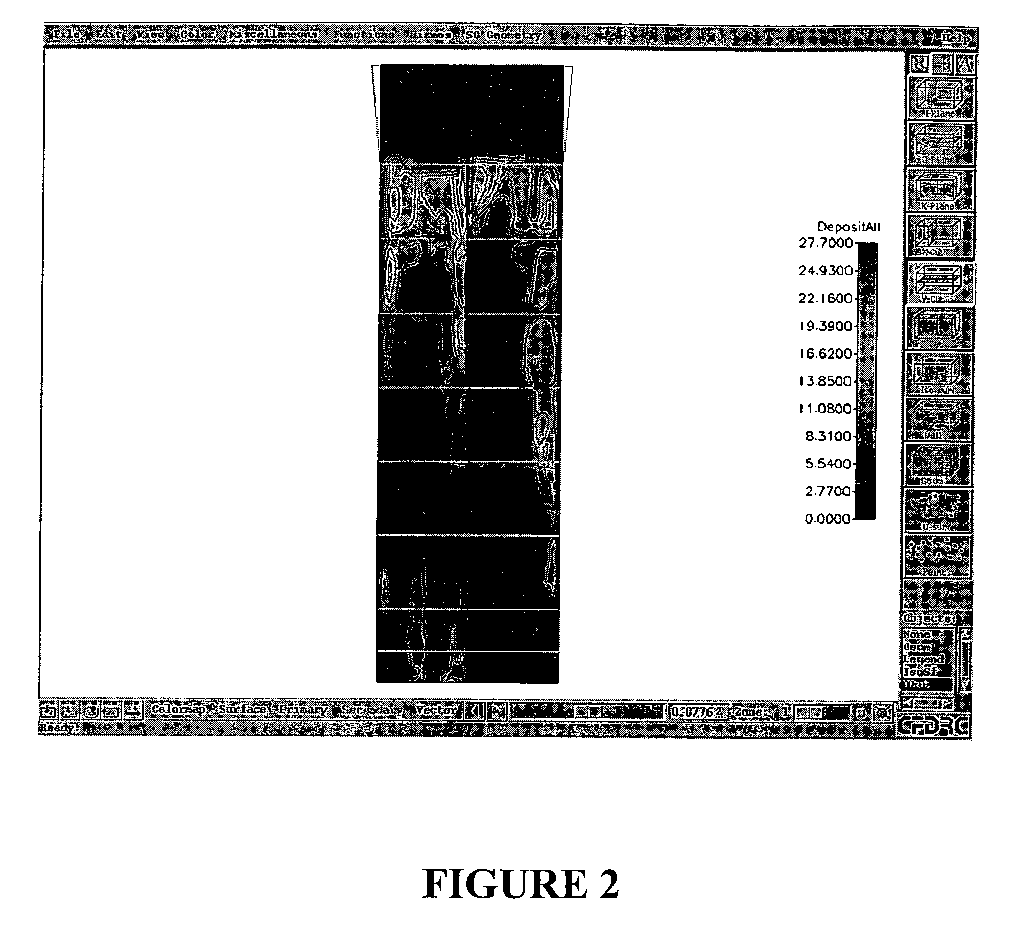
[0018]Referring to FIG. 5, a deposit mapping methodology 10 is provided to ascertain the location and amounts of accumulated material inside a steam generator. The steam generator may be part of a nuclear or non-nuclear system. The accumulated material may be from corrosion products generated inside the plant as well as feedwater impurities inside the coolant as it flows through the steam generator.

[0019]The purpose of the deposit mapping methodology 10 is to provide characterization of the amounts of deposit loading as well as the deposit distribution of materials present in a steam generator as the feedwater passes through a steam generator. Knowledge of the deposit condition within a steam generator is valuable for assessing the impact of the deposit on thermal hydraulic performance, on the potential for accelerated corrosion of the heating surfaces within the steam generator, as well as determining a degradation of Non Destructive Examination (NDE) signal detection performance. ...


PUM

PropertyMeasurementUnit
lengthaaaaaaaaaa
thicknessaaaaaaaaaa
eddy currentaaaaaaaaaa

Abstract

A method to determine deposits in a steam generator having the steps of creating a calibration standard having at least two rings of deposit material, subjecting the calibration standard to an eddy current signal, wherein an amplitude of the signal reflected from the calibration standard is used to obtain a polynomial equation fit of the reflected eddy current signals to actual thickness of the rings, obtaining a steam generator with tubes, initiating an eddy current signal into the tubes of the steam generator, detecting and recording reflections of the eddy current signal initiated into the tubes of the steam generator, and determining a thickness of the deposits in the steam generator from the recorded reflections of the eddy current signal and the polynomial equation.

Description

FIELD OF THE INVENTION[0001]The present invention relates to steam generators. More specifically, the present invention provides a steam generator deposit mapping system and methodology.BACKGROUND INFORMATION[0002]Nuclear steam generators used in pressurized water reactors, for example, are subject to the accumulation of feedwater impurities. Although the feedwater is maintained at a high level of purity, minute concentrations of corrosion products and / or feedwater impurities may be concentrated in the flow stream, consequently leading to buildup of these materials within the steam generator as the water is converted into steam. These deposits will eventually degrade the thermal hydraulic performance of the component.[0003]To increase the heat transfer capabilities of the steam generator, the thickness of the deposits, as well as the locations of the deposits, must be determined such that removal techniques may be implemented. Currently, visual inspections and eddy current inspectio...

Claims


Application Information

Patent Timeline
Patent Type & Authority Patents(United States)
IPC IPC(8): G01N27/72
CPCG01B7/06G01B7/105G01B21/042G01N17/008Y02E30/30G06F17/00G21C17/032G21C19/20
Inventor WYATT, JOSEPH R.GRIFFITH, JOHNNEWMAN, VICTORFLECK, JEFFREY M.
Owner AREVA NP INC
Learn More