
High temperature thermistors

a technology of ceramic thermistors and thermistors, which is applied in the direction of positive temperature coefficient thermistors, resistors adapted for applying terminals, semiconductor devices, etc., can solve the problems of increasing the cost of production, difficult to reproduce the electric performance of these devices (resistivity value and temperature dependence of resistivity), and difficult to interchange ceramic thermistors

Inactive Publication Date: 2008-07-29
ADSEM
View PDF35 Cites 4 Cited by
  • Summary
  • Abstract
  • Description
  • Claims
  • Application Information

AI Technical Summary

Benefits of technology

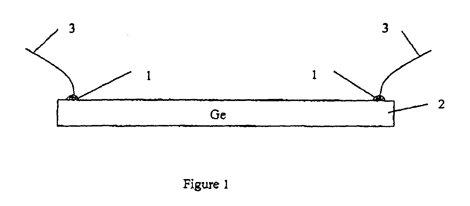
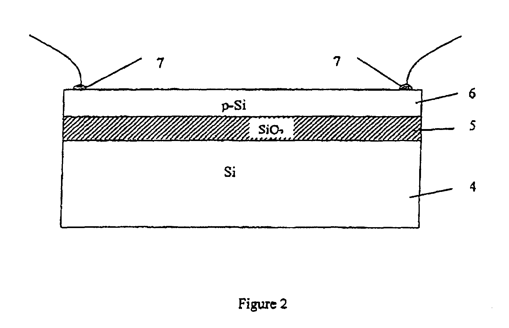
"The present invention provides a high temperature NTC thermistor that has a polycrystalline thermistor body made of polycrystalline Si or polycrystalline Ge with intrinsic conductivity. The thermistor has at least one ohmic contact on its surface. This invention solves the shortcomings of the existing art and improves the performance of the thermistor."

Problems solved by technology

This makes electrical performance of these devices (resistivity value and temperature dependence of resistivity) difficult to reproduce with a high accuracy.
As a result, ceramic thermistors are not interchangeable, and for high accuracy temperature measurements it is necessary to calibrate them for different temperature ranges.
This significantly increases the cost of production.
As a result, the sensitivity of these thermistors is not very high.
Their maximum working temperature range does not exceed 350° C. Thus, low performance, lack of a wide working temperature range, poor interchangeability and high production costs are disadvantages of high temperature ceramic NTC thermistors.

Method used


Image

  • High temperature thermistors
  • High temperature thermistors
  • High temperature thermistors

Examples


Embodiment Construction

[0011]Reference will now be made in detail to the preferred embodiments of the invention, examples of which are illustrated in the accompanying drawings. While the invention will be described in conjunction with the preferred embodiments, it will be understood that they are not intended to limit the invention to these embodiments. On the contrary, the invention is intended to cover alternatives, modifications and equivalents that may be included within the spirit and scope of the invention as defined by the appended claims. Furthermore, in the following detailed description of the present invention, numerous specific details are set forth in order to provide a thorough understanding of the present invention. However, it will be obvious to one of ordinary skill in the art that the present invention may be practiced without these specific details. In other instances, well known methods, procedures, components, and circuits have not been described in detail as not to unnecessarily obsc...


PUM

PropertyMeasurementUnit
thicknessaaaaaaaaaa
thicknessaaaaaaaaaa
thicknessaaaaaaaaaa

Abstract

A high temperature NTC thermistor includes a polycrystalline thermistor body, selected from a list consisting of polycrystalline Si with intrinsic conductivity and polycrystalline Ge with intrinsic conductivity. At least one ohmic contact is disposed on at least one surface of the polycrystalline thermistor body.

Description

RELATED APPLICATIONS[0001]This is a divisional application of application Ser. No. 10 / 846,055, filed on May 15, 2004, now U.S. Pat. No. 7,306,967, which in turn claims priority to the provisional U.S. patent application Ser. No. 60 / 473,753, filed on May 28, 2003.BACKGROUND OF THE INVENTION[0002]1. Field of the Invention[0003]This invention relates to the art of semiconductor device manufacturing, and more specifically, to the production of negative temperature coefficient (NTC) and positive temperature coefficient (PTC) semiconductor thermoresistors based upon Si and / or Ge for a temperature range of between −50° C. to +500° C.[0004]2. Discussion of the Background Art[0005]Semiconductor NTC thermistors for high temperature measurements are based upon ceramic materials and produced from of a mix of metal oxides such as Mn, Fe, Co, Ni, and Zn. Such thermistors are the main type of high temperature thermistors employed in the industry, and have been for many years. The electroconductivi...

Claims


Application Information

Patent Timeline
Patent Type & Authority Patents(United States)
IPC IPC(8): H01L29/04
CPCH01C17/28H01C7/042H01C7/02
Inventor KOZHUKH, MICHAEL
Owner ADSEM
Learn More