
Estimating method and apparatus and estimating program of wire harness and recording medium thereof

a technology of estimating program and wire harness, which is applied in the direction of instrumentation, transportation and packaging, design optimization/simulation, etc., can solve the problem of the amount of change of wire harness, and achieve the effect of easy instruction and easy instruction

Inactive Publication Date: 2008-07-22
TOYOTA MOTOR EAST JAPAN
View PDF18 Cites 9 Cited by
  • Summary
  • Abstract
  • Description
  • Claims
  • Application Information

AI Technical Summary

Benefits of technology

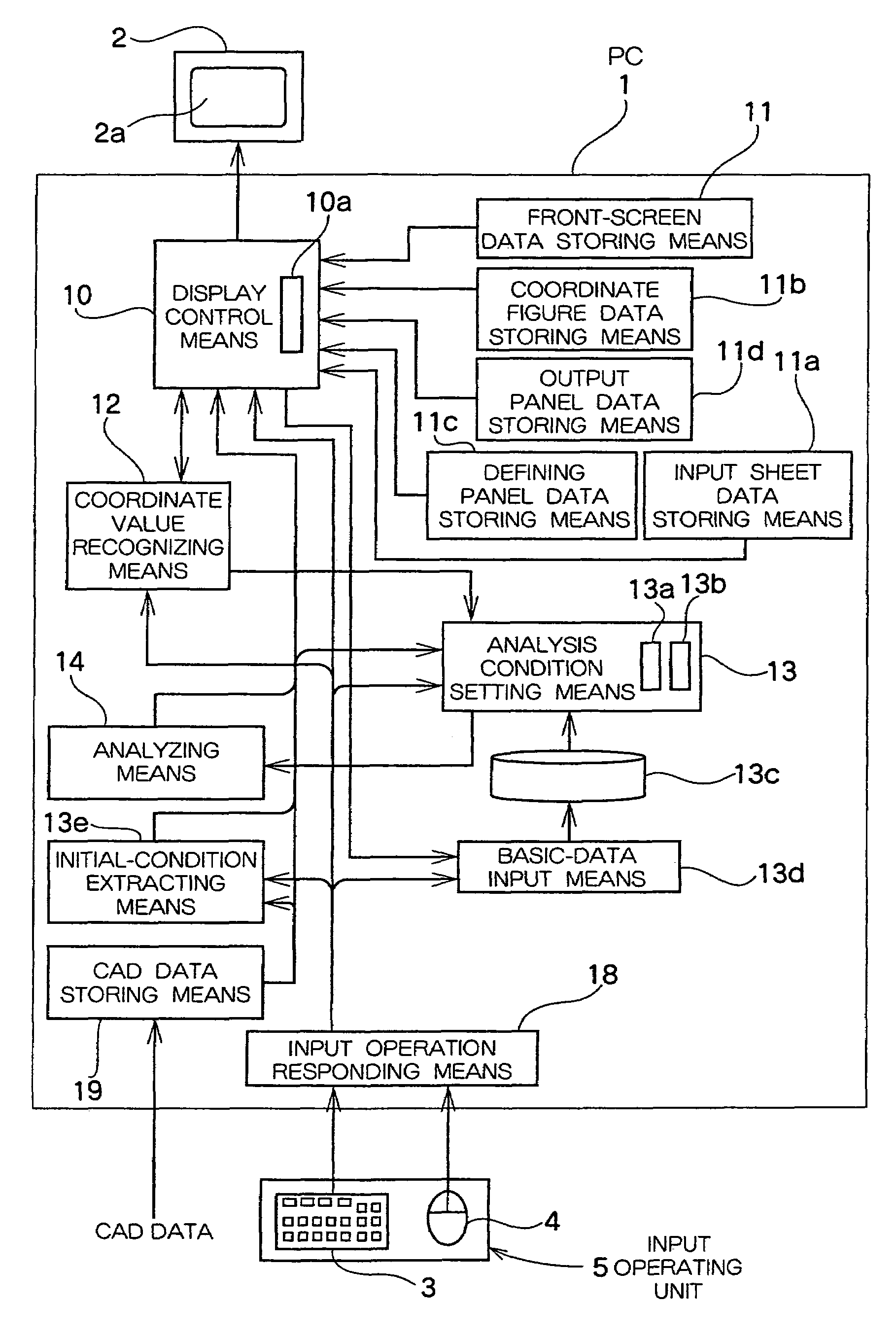
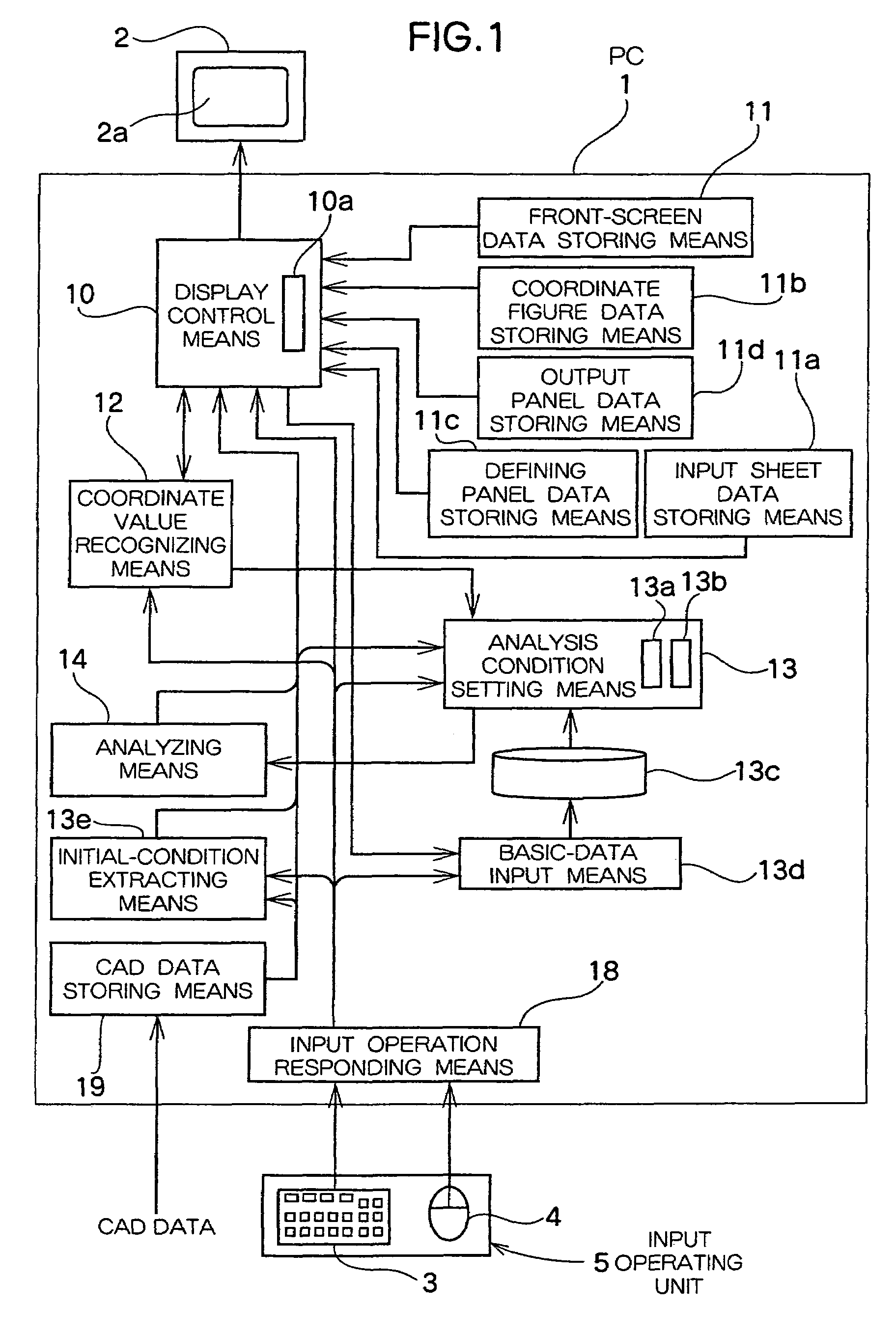
[0009]Thus, the three-dimensional wiring shape including the connector of the wire harness corresponding to the moving position of the connector at the distal end thereof is displayed on the screen of the display unit, together with the reactive force upon grasping the connector. The input operation desirably sets, as the analysis condition, the physicality and shape of the wire harness and the property of a constraining member such as a connector on the screen for setting the condition, thereby estimating the wiring shape and the reactive force on the screen. Therefore, it is possible to estimate the wiring properties including the over-length or short length of the wire harness, interference with a peripheral part or interference with peripheral part due to the vibration in the attaching state, and load of connector operation, and the degree of depending on the test device of the wire harness is reduced or eliminated.
[0011]Thus, the screen of the display unit displays the wiring shape on the three dimensions including the connector of the wire harness corresponding to the moving position of the connector at the distal end thereof together with the reactive force in the state for grasping the connector. Further, it is possible to recognize the coordinate value of the position on the moving destination of the instructing position in the halfway of the wire harness, instructed by the input operation between the constraining positions, as well as the coordinate value of the connector at the distal end thereof and to display the wiring shape. Further, the material, shape, and constraining condition of the wire harness are variously considered on the screen, thereby easily estimating the wire harness on the screen. Therefore, the degree of depending to the test of the wire harness is reduced or is eliminated.
[0015]In order to easily set the position on the moving destination of the instructing position on the screen, the display control means displays a local coordinate figure of the virtual three-dimensional shape image having three axes having one axis set in the wiring direction of the wire harness with the position on the screen instructed by the input operating unit as the origin, and the coordinate recognizing means outputs a coordinate value on a CAD coordinate system corresponding to the amount of movement set in the image for setting the analysis condition and the moving direction of the position on the local coordinate figure instructed by the input operating unit. Thus, it is possible to easily set the moving destination of the instructing position of the wire harness on the local coordinate system.
[0018]In order to estimate the interference with the peripheral parts, the CAD data includes data for prescribing the arrangement position and the three-dimensional shape of a peripheral component which might interference with the wire harness. Thus, the image of the part with the interference is displayed, thereby estimating the interference with the peripheral part with high precision.
[0019]In order to easily instruct the instructing position, the distal end and the base end of the wire harness and the halfway position for changing the material of the wire harness are prescribed in advance as specific points of the positions to be instructed by the input operating unit, and the specific points are displayed as point marks on the virtual three-dimensional shape image. Thus, it is possible to easily instruct, by a mouse, the important instructing position upon estimating the constraining position of the wire harness and the position of the span boundary.

Problems solved by technology

However, the design of wire harness must be further viewed about conditions of the interference with peripheral parts due to the deformation in the connector detaching state at the distal end of the wire harness, the operating load due to the reactive force to the wire harness in the parallel advancing direction or rotating direction upon attaching the connector, the fluctuation of deformation due to the tolerance of the wire-harness length, and the amount of change in wire harness due to the vibration.

Method used


Image

  • Estimating method and apparatus and estimating program of wire harness and recording medium thereof
  • Estimating method and apparatus and estimating program of wire harness and recording medium thereof
  • Estimating method and apparatus and estimating program of wire harness and recording medium thereof

Examples


Embodiment Construction

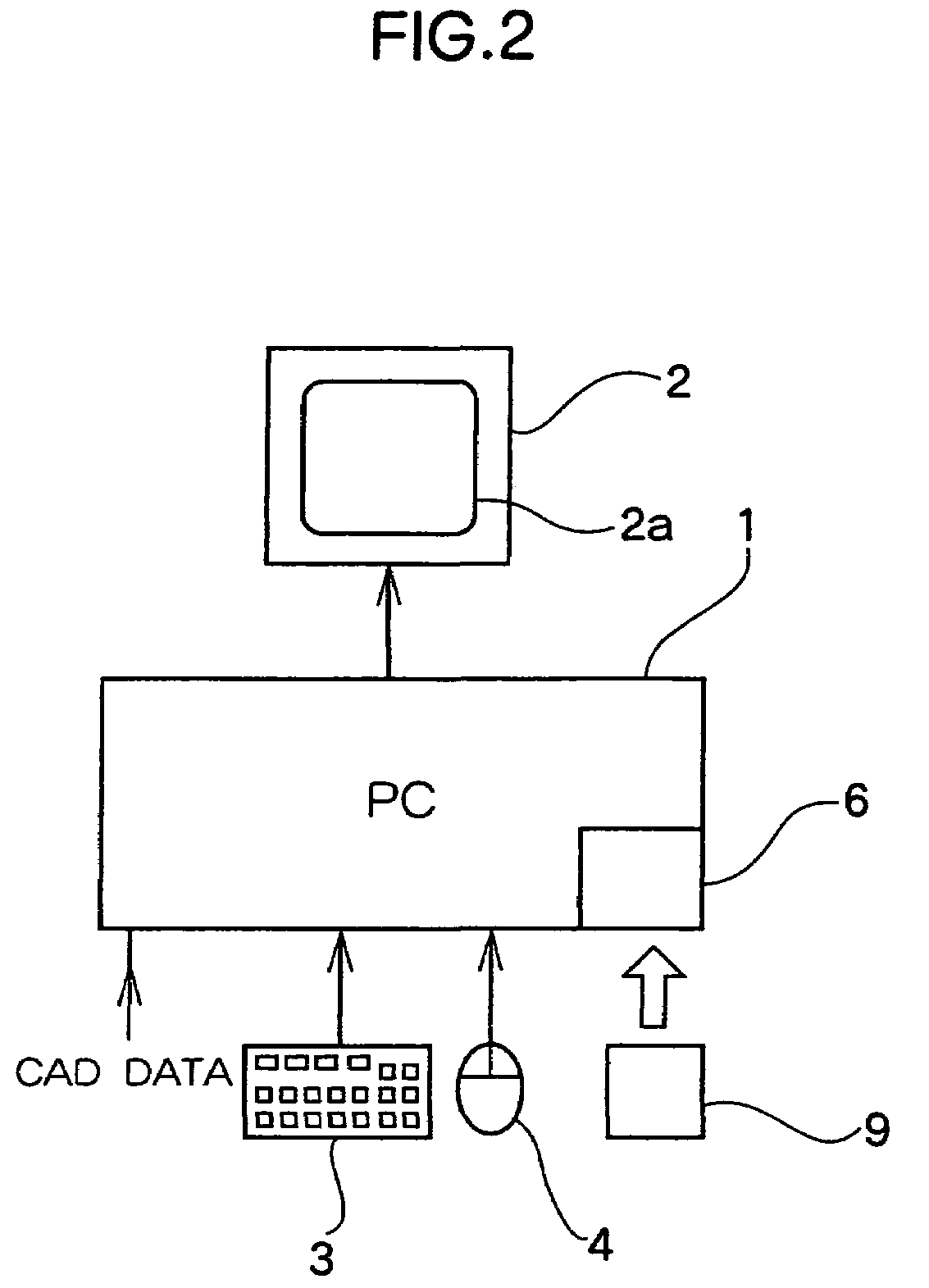
[0032]A description is given of an estimating apparatus which executes an estimating method of a wire harness according to the embodiment of the present invention with reference to FIGS. 1 to 12. The estimating apparatus uses a personal computer (PC) 1 comprising, as attachments, a display unit 2 and an input operating unit 5 such as a keyboard 3 and a mouse 4. A recording medium 9 such as a CD to which a program of an estimating apparatus of the wire harness is recorded is set to a disk drive 6. CAD data on the wiring shape of the wire harness at a plurality of areas as an estimating target, designed by a CAD device, on the three-dimensional model is loaded to the memory incorporated in the personal computer 1, thereby enabling the estimation. Incidentally, the CAD data is captured from the disk drive 6 via the recording medium 9 depending on the cases.

[0033]The loaded estimating program operates the included memory and the CPU so as to function the personal computer 1 as the follo...


PUM


Abstract

In order to analyze, by a finite element method, the wiring property of a wire harness having a base end constrained and a distal end having a connector constrained to a connector base, a screen of a display unit displays a virtual three-dimensional shape image of the wire harness including the connector, using CAD data formed for designing the three-dimensional wiring shape and a condition setting screen for setting one part of analysis conditions, which is not included in the CAD data, of the property, the shape, a constraining position, and a constraining direction of the wire harness by input operation. The position on the moving destination of the connector, designated on the virtual three-dimensional shape image, is recognized as a coordinate value of the constraining position. The wiring shape of the wire harness and the reactive force upon grasping the connector by the FEM are analyzed under the analysis condition included in the CAD data, the analysis condition set on the condition setting screen, and the analysis condition necessary for estimating the constraining position prescribed by the coordinate value. The analysis of the virtual three-dimensional shape image of the analyzed wiring shape including the connector and of the reactive force is displayed on the screen.

Description

BACKGROUND OF THE INVENTION[0001]1. Field of the Invention[0002]The present invention relates to estimating method and apparatus and an estimating program of a wire harness, and a recording medium thereof, in which the wiring property, such as the wiring shape, of a wire harness whose base ends are constrained and which have connectors constrained by connector bases at distal ends thereof, is estimated by FEM (Finite Element Method) and the analysis result is estimated on the screen of a display unit.[0003]2. Description of the Related Art[0004]For example, Japanese Unexamined Patent Application Publication No. 2002-373533 discloses a virtual method of a wire harness comprising: a data input step of three-dimensional design data of the wire harness wired on a vehicle; an image display step of displaying an image of a reference wiring data as a background image on the three-dimensional virtual space; a three-dimensional design data display step of overlaying and displaying the three-...

Claims


Application Information

Patent Timeline
Patent Type & Authority Patents(United States)
IPC IPC(8): G06F19/00
CPCB60R16/0207G06F17/5095G06F17/5018G06F2217/36G06F30/15G06F30/23G06F2113/16
Inventor YAMANE, SATSUKI
Owner TOYOTA MOTOR EAST JAPAN
Learn More