
RFID tag circuits operable at different speeds

a technology of rfid tag circuit and different speed, which is applied in the direction of instruments, liquid/fluent solid measurement, generating/distributing signals, etc., can solve the problems of low power to the circuit and large reading distance from the reader, and achieve the effect of reliable power and higher speed

Active Publication Date: 2008-07-22
IMPINJ
View PDF3 Cites 20 Cited by
  • Summary
  • Abstract
  • Description
  • Claims
  • Application Information

AI Technical Summary

Benefits of technology

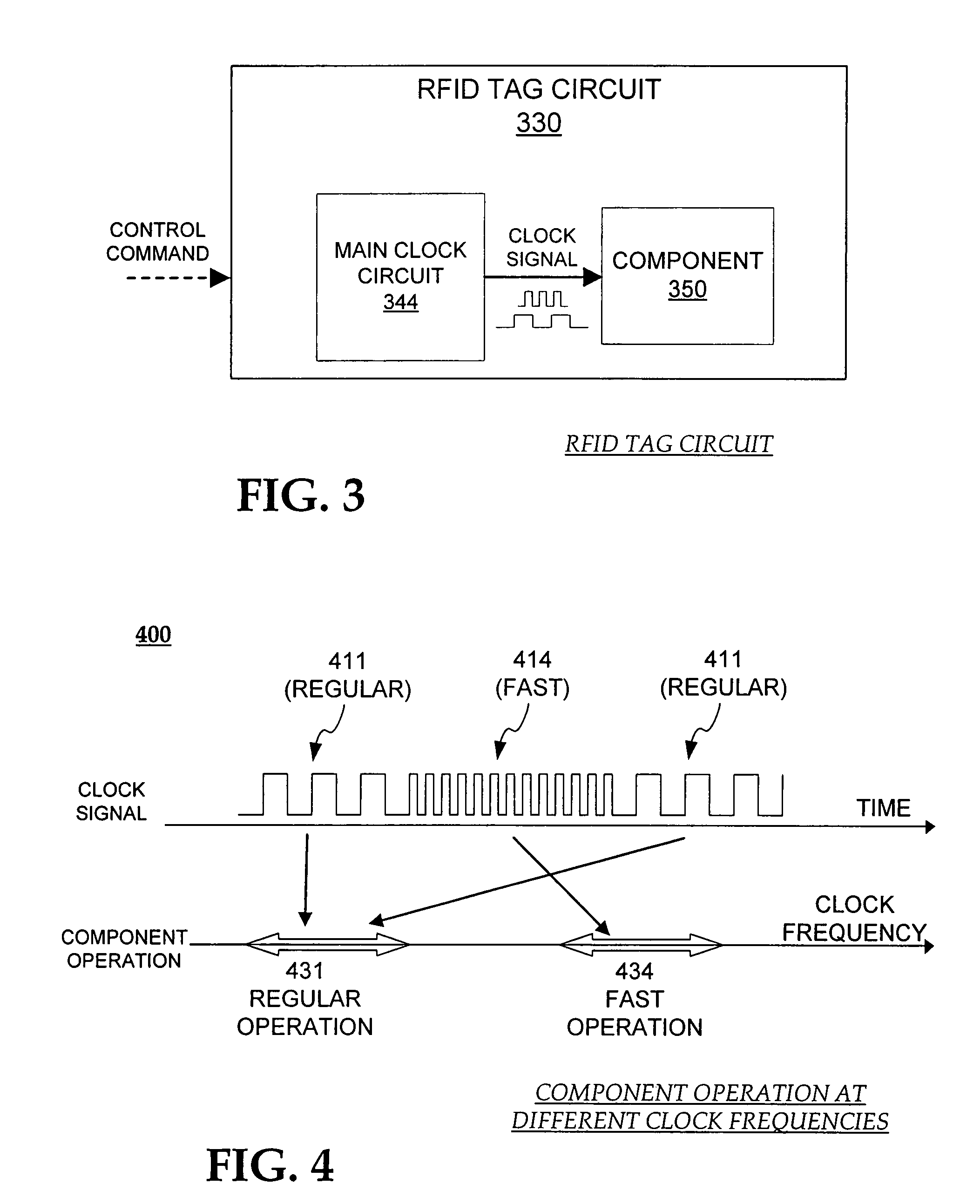
[0012]In addition, the circuit is amenable to operating at a different, substantially higher speed. This is done for certain reading conditions where it is known that the reader will be close to the circuit. The proximity ensures that the chip generates reliably more power, which enables its operation at the higher speed.
[0013]An advantage over the prior art is that the RFID tag chip can be read and / or written to faster. This helps in a number of field reading situations, and in production throughput.

Problems solved by technology

These conditions include potentially a large reading distance from the reader, with correspondingly low power to the circuit.

Method used


Image

  • RFID tag circuits operable at different speeds
  • RFID tag circuits operable at different speeds
  • RFID tag circuits operable at different speeds

Examples


Embodiment Construction

[0029]As has been mentioned, the present description is about RFID tag circuits that are operable at different speeds, and related methods. Certain details are set forth below to provide a sufficient understanding of the invention. However, it will be clear to one skilled in the art that the invention may be practiced without these particular details. Moreover, the particular embodiments of the present invention described herein are provided by way of example and should not be used to limit the scope of the invention to these particular embodiments. In other instances, well-known circuits, control signals, timing protocols, and software operations have not been shown in detail in order to avoid unnecessarily obscuring the invention.

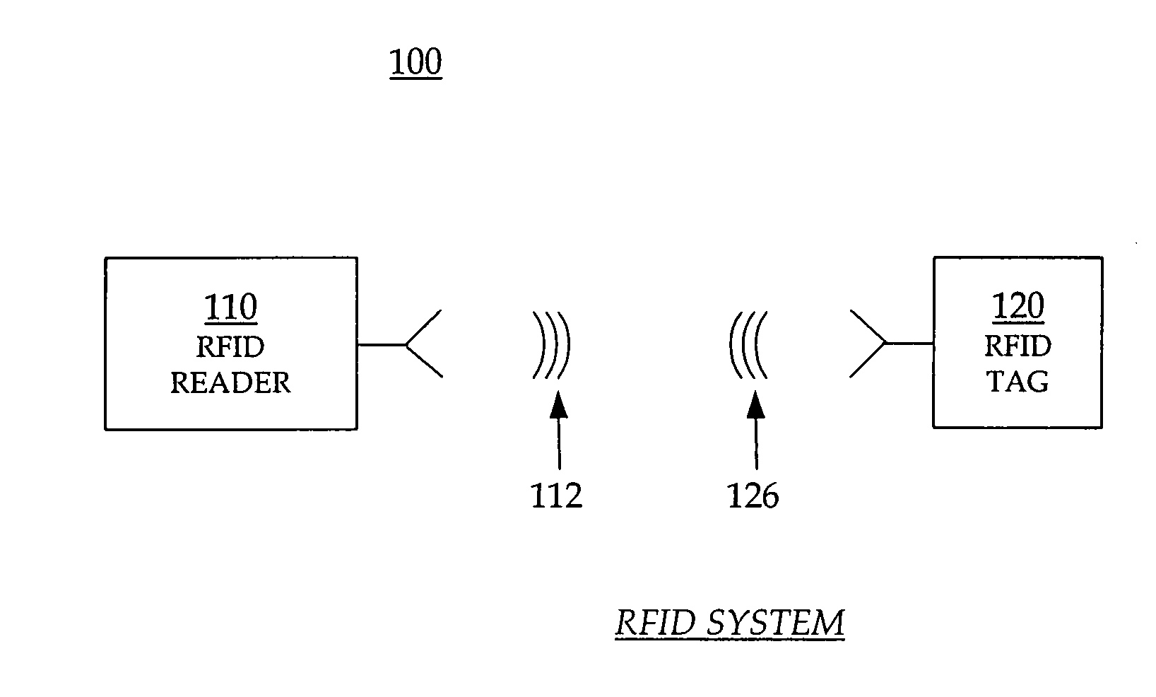
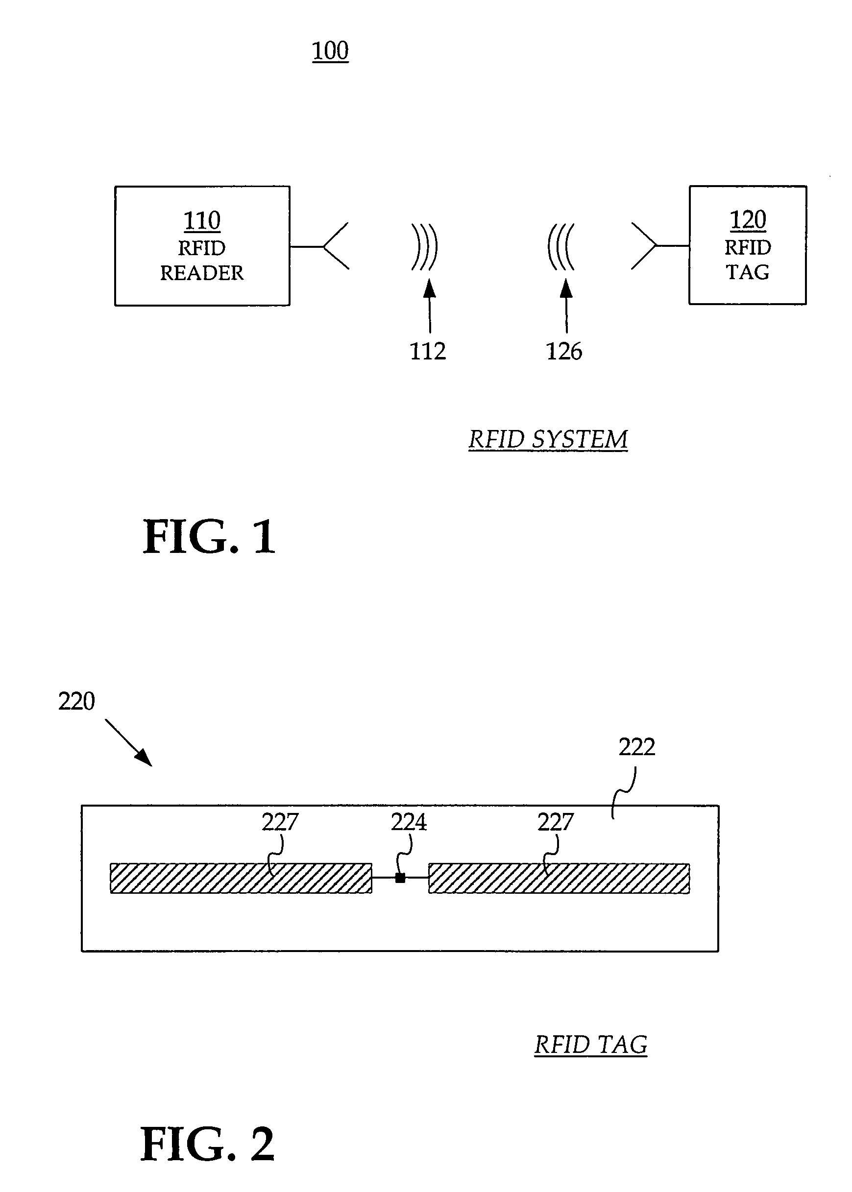
[0030]The subject is now described in more detail. FIG. 1 is a diagram of a typical RFID system 100, incorporating aspects of the invention. An RFID reader 110 transmits an interrogating Radio Frequency (RF) wave 112. RFID tag 120 in the vicinity of RFID ...


PUM


Abstract

Embodiments of RFID tag circuits and methods are described, which include a chip having a clock circuit operable to generate a clock signal having different frequencies, and one or more components operable to work at the different frequencies. In addition to a regular frequency, at least one higher frequency is possible, which is enabled in situations where a reader is known to be close to the chip. The proximity ensures that the chip generates reliably more power, which enables its operation at the higher speed.

Description

CROSS REFERENCE TO RELATED PATENT APPLICATIONS[0001]This patent application claims priority from U.S.A. Provisional Patent Application No. 60 / 773,723, filed on 2006 Feb. 15, the disclosure of which is hereby incorporated by reference for all purposes.BACKGROUND[0002]1. Field of the Invention[0003]The present description is related to the field of Radio Frequency Identification (RFID) systems, and more specifically to RFID tag circuits that are operable at different speeds, and related methods.[0004]2. Description of the Related Art[0005]Radio Frequency IDentification (RFID) systems typically include RFID tags and RFID readers (the latter are also known as RFID reader / writers or RFID interrogators). RFID systems can be used in many ways for locating and identifying objects to which the tags are attached. RFID systems are particularly useful in product-related and service-related industries for tracking large numbers of objects being processed, inventoried, or handled. In such cases, ...

Claims


Application Information

Patent Timeline
Patent Type & Authority Patents(United States)
IPC IPC(8): G08B13/14
CPCG06K19/0723
Inventor KOEPP, RONALD LEEPESAVENTO, ALBERTOCOLLERAN, WILLIAM T.
Owner IMPINJ
Learn More