
Plate for running shoe

a technology for running shoes and elastic plates, applied in the field of shoes, can solve the problems of not being able to achieve the intended effect, the return of invested energy, and the insufficient transmission of the spring force of the elastic plates during push-off to the complete foo

Inactive Publication Date: 2008-07-22
ADIDAS
View PDF20 Cites 91 Cited by
  • Summary
  • Abstract
  • Description
  • Claims
  • Application Information

AI Technical Summary

Benefits of technology

[0009]It is therefore one object of the present invention to provide a shoe, in particular a sprint shoe, with a bending elastic plate, where the plate effectively catapults the complete foot in a forward direction when it springs back, and supports the complete foot during the course of movements of the athlete.
[0011]Because the plate covers substantially the complete length of the shoe, its stiffness determines the elastic properties of the shoe. The planar shape in the forefoot part acts like a “leaf spring,” which is deflected during each step in the rolling-off phase and which elastically springs back during pushing off into its original planar shape. The elasticity of the forefoot part of the plate assures that the energy invested for the deflection of the “leaf spring” is essentially regained without any loss.
[0012]The rearfoot part of a plate in accordance with the invention has a different primary objective. Since the foot of a sprinter is encompassed three-dimensionally, the rearfoot part of the plate is comparatively rigid and therefore transmits, with minimal loss, the springing back of the plate to the complete foot including the heel. The damping of the rearfoot part stressed in the prior art is not necessary in sprint shoes, because during the sprint, the athlete runs exclusively on the forefoot part without contacting the ground with the heel.
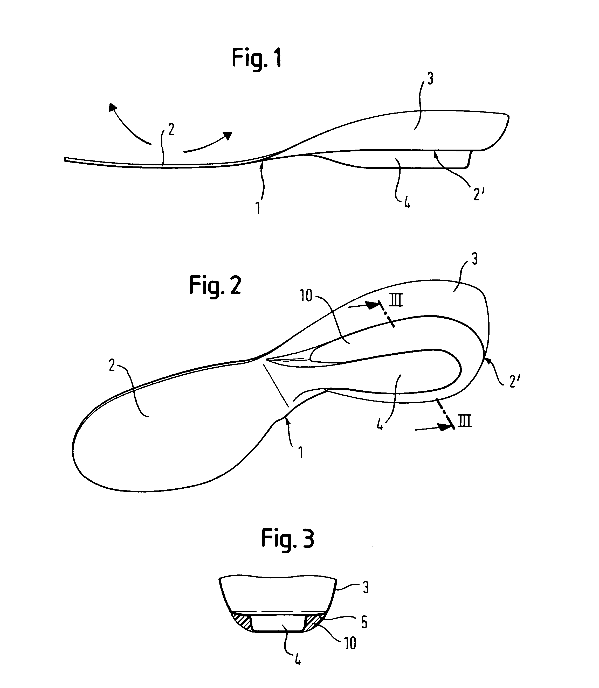
[0013]In various embodiments, the forefoot part has a stiffness of between about 40 N / mm and about 120 N / mm, and preferably between about 60 N / mm and about 100 N / mm, measured according to ASTM 790. The plate has an associated energy loss as a result of bending the forefoot part of the plate of less than about 5%. The rearfoot part can include a heel cup that cradles the foot, a wedge- or rib-like raised portion disposed beneath the rearfoot part, specifically located beneath the heel cup if the plate is so equipped, and at least one damping element disposed beneath the rearfoot part. The heel cup effectively supports the foot against turning to the medial or lateral side and reduces the danger of injuries of the foot, ankle, and knee joints. In one embodiment, the damping element can extend around the rib-like raised portion and / or is horseshoe shaped. In situations where the rearfoot part contacts the ground, for example during normal walking, an additional damping element can be arranged below the heel cup. The additional damping element is effective during slightly sideways ground contact of the heel. When the rib-like raised portion is arranged below the heel cup, it brings the foot into a forward position during running, which facilitates running on the forefoot part without ground contact of the heel. In another embodiment, the stiffness of the forefoot part is greater than the stiffness of the rearfoot part. This would result in, for example, a “leaf spring” action of the forefoot part, and at the same time a softer and therefore more comfortable rearfoot part.

Problems solved by technology

Sprint shoes according to the above discussed prior art however, have the disadvantage that the spring force of the elastic plate is not sufficiently transmitted during push-off to the complete foot.
In particular, the heel part is not sufficiently included in the overall procedure due to the softer materials provided in the heel part.
Although the plate itself stores energy elastically, with minimal losses, the return of invested energy, the intended effect, is only partially achieved.

Method used


Image

  • Plate for running shoe
  • Plate for running shoe
  • Plate for running shoe

Examples


Embodiment Construction

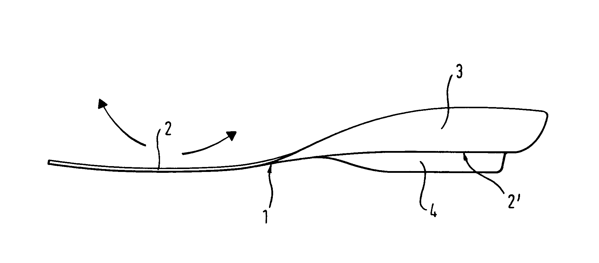
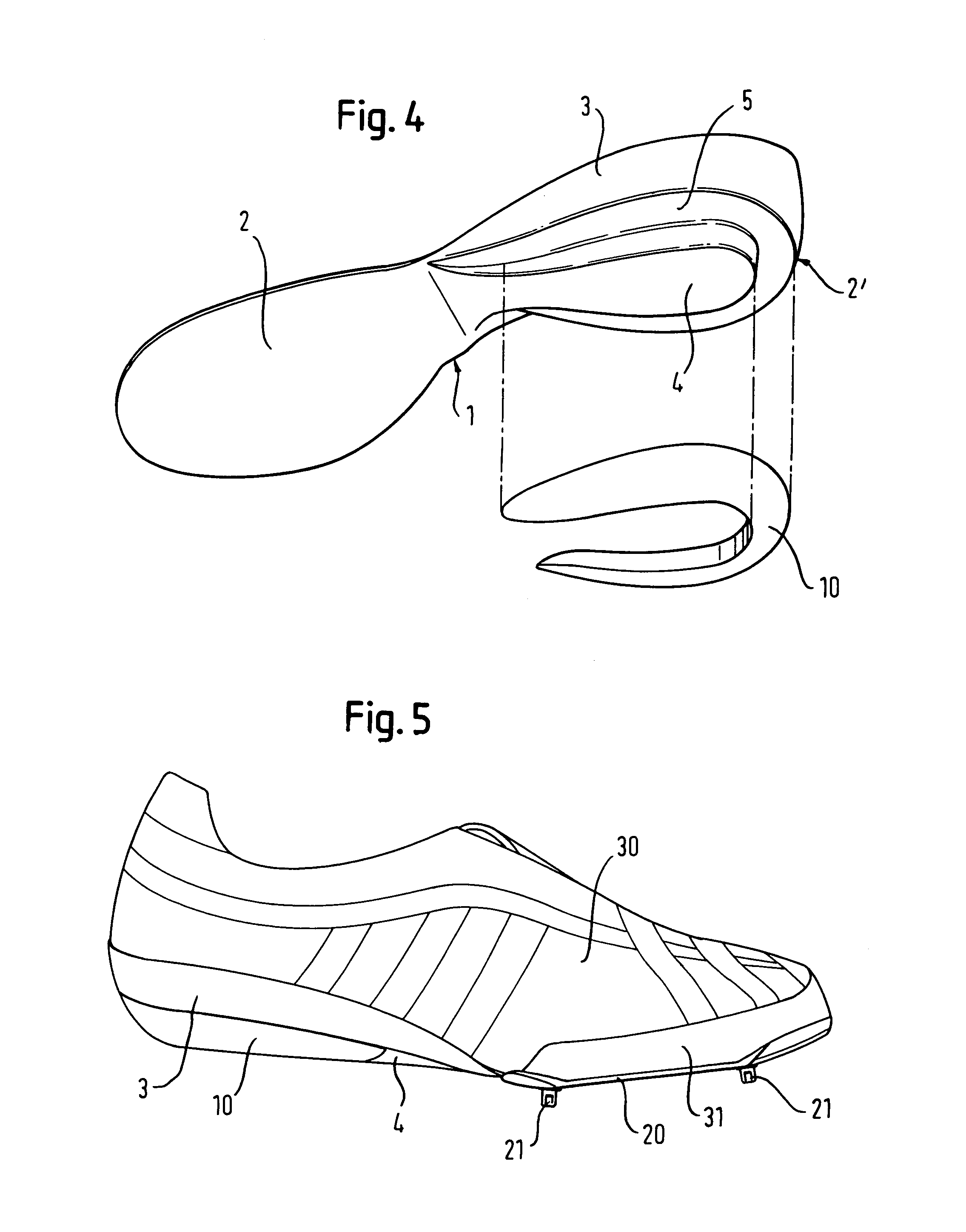
[0028]With reference to FIG. 1, a sports shoe according to the invention includes a plate 1 arranged in the sole area of a foot. For simplicity, only the plate 1, together with an optional damping element 10, is shown in FIGS. 1 through 4. The exact arrangement within the sole area of the shoe is discussed further below, with reference to FIGS. 5 through 7.

[0029]As depicted in FIG. 1, the plate 1 includes a generally planar forefoot part 2. The forefoot part 2 may have a thickness of about 1 mm. The thickness of the forefoot part 2 may vary depending on the material used. The material for the spring plate is typically a composite material. Composite materials may include: graphite, fiberglass, carbon fibers embedded in a matrix of resin, or para-aramid fibers, such as the Kevlar® brand sold by DuPont. These materials combine high stiffness and low energy loss with low weight. Alternatively, the use of spring steel or other elastic metal alloys is possible. Further, suitable plastic ...


PUM

PropertyMeasurementUnit
Fractionaaaaaaaaaa
Stiffnessaaaaaaaaaa
Stiffnessaaaaaaaaaa

Abstract

The invention relates to a shoe, in particular a sprint shoe, including a plate arranged in a sole area of the shoe. The plate extends essentially over the complete length of the sole area and is substantially planar in a forefoot part and is constructed of a material and configured to allow for elastic bending of the plate in the longitudinal direction, and is configured to three-dimensionally encompasses a rearfoot part of the foot. Optionally, the plate includes a heel cup in the rearfoot part to cradle the foot. Further, a wedge- or rib-like raised part may be arranged below the heel cup.

Description

CROSS-REFERENCE TO RELATED APPLICATIONS[0001]This application incorporates by reference, and claims priority to and the benefit of, German patent application serial number 19919409.2, which was filed on Apr. 28, 1999, and European patent application no. 00103409.9, which was filed on Feb. 24, 2000.TECHNICAL FIELD[0002]The invention relates to articles of footwear such as sports shoes, in general, and in particular to a sprint shoe with a plate arranged in the sole area.BACKGROUND INFORMATION[0003]Sport shoes for track and field competitions, in particular for sprinting over short distances, have conflicting requirements. For example, the shoes should be as lightweight as possible, because the weight of the shoes can obstruct fast movements of an athlete during the sprint. The importance of lightweight construction follows from the fact that a reduction of the weight of the shoe by 30 g leads to a reduction of energy consumption during running of 0.3%; however, the shoes must have su...

Claims


Application Information

Patent Timeline
IPC IPC(8): A43B7/14A43B1/10A43B13/02A43B13/04A43B13/24A43B13/38A43B23/00A43B13/12A43B13/18
CPCA43B5/049A43B13/10A43B13/183A43B13/188A43B13/12
Inventor SCHOLZ, WOLFGANGNORTON, DANIEL EUGENECARLUCCI, PATRIZIOKRABBE, BERTHOLDBERGER, CHRISTOPH
Owner ADIDAS
Learn More